A few months back—June 2013 issue, to be exact—we half-tackled the steering on our 1933 Tudor project. I say half only because that's just what we did, the lower "half" of the Vega-based cross steer setup. The remaining portion, that being everything above the Borgeson Universal Company box (as with most things on the build), was still in the air at that point regarding what Jimmy White and I would need to complete the steering.
You may have noticed that for mock-up purposes, we'd incorporated an original '37 Ford steering column, complete with banjo wheel. A then-reluctant White eventually gave in, literally, offering up the parts for the cause. That was/is great for me, as it made for one less item (or if you dissect everything, "items") to procure for the project. Ultimately, it truly fit the cause—nice, excuse the term, patina, bolted right up to the sedan's dash, and had already been severed from its original box. (Later, as you're about to learn, that last part would play a near-pivotal role, no pun intended.)
So, for the time, the 1937 wheel and column hung proudly till we could focus our attention back to finishing up the steering. Well, that time has finally come. With the Borgeson box mounted and ancillary tie-rod/draglink connections made, the linkage continued between box and column.
Initially, I—not being as well versed on early Ford mechanical gear as I should—assumed the steering column's output shaft was "OE", simply what you'd have once the steering box itself had been peeled away from the column. Despite Jimmy's doubts, I proceeded by ordering a U-joint from Borgeson to fit the protruding splines and diameter of the steering shaft. Borgeson themselves questioned the application, but still sent what I requested, a 9/16-26xDD stainless joint (along with a 3/4-36xDD for the Vega box, as a length of stainless DD shaft for the intermediate connection). And so as I always do things—backward—I went to separate the shaft from the column after receiving the goods. Alas, everyone's disbelief was confirmed: rack-and-pinion input shaft.
Now, what's a 9/16-inch diameter shaft doing on a 1930s Ford steering column, you ask? Well, I'll tell you: at some point in time, someone, after severing the column from the box (the only part I got right), welded—very professionally I might add—a short section of steering shaft to the column, assumedly for the same purposes as ours. Now, under normal circumstances—and I highly stress that—welding steering shafts is a no-no. However, this had been done so well (not only was it perfectly TIG welded, it had been properly pinned in not one, but three spots) that I felt comfortable using it. Beyond the mating aspects, whoever performed the work also outfitted the column with Delron bushings top and bottom (along with a caged roller bearing below), disabled the stock ignition lockout, and as mentioned, it "fit" our application. We just had to clean everything up and make the proper connections. (Note: we don't recommend modifying steering shafts whatsoever. Manufacturers such as Borgeson and CPP make new shafts. Any compromise in a mechanical part as crucial as a steering shaft is a potential compromise to you and your passengers' personal safety!)
With column hung, parts in hand, and time to burn, we finally knocked out the remainder of the Tudor's steering—and made it possible, when necessary, to move the sedan around the shop without the aid of Go-Jacks!
 1. Three items were all that held us up from completing the steering on the 1933 Tudor: two joints and a shaft. That, and whether or not we were going to move forward with the 1937 Ford column we’d been using for mock-up purposes up until this point.
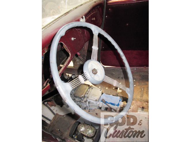
 2. After convincing Jimmy White to relinquish one of his early Ford treasures—for a nominal fee, of course—the banjo-wheeled setup was now part of the build, officially. It fit (physically), it looked like it belonged in the 1933, and, well, it was already in the car! Could you ask for more? However, it wasn’t without inherent flaws, as we’re about to reveal.
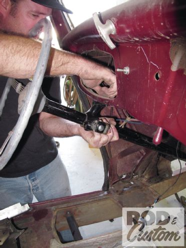
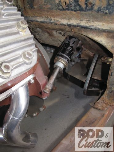 3. True early Ford experts will quickly recognize—this is no early Ford steering shaft end. I am no true early Ford expert … not by a longshot. It is Ford, however, just not of early nature. Turns out that, somewhere during its post-OE life, the 1937 column had been modified for later-model steering, thus the smaller-diameter splined output shaft (as opposed to a hollowed, severed shaft). Note: steering shaft alteration is NOT recommended; seek alternative means (new shaft/column) whenever possible, and if modification is done, have it done by a professional.
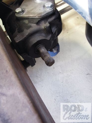 4. Despite having a seemingly questionable steering column lower end, our box—a Borgeson Universal Company Vega unit—was anything but. The output of this particular steering gear is 3/4-inch diameter 36-spline shaft; the column’s "particular" end, rather, the rack-and-pinion shaft section, is 9/16-inch diameter 26-spline.
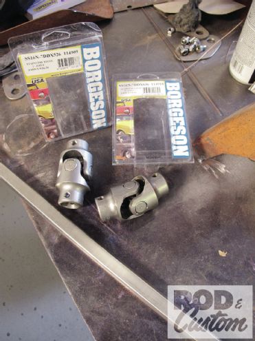
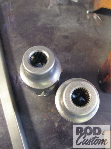 5. Steering couplers/joints/knuckles come in all shapes and sizes (for more on specifics, see illustrations).
 6. For street rod applications, the variables are lessened: typically you’re dealing with splines and, as Borgeson calls them, “irregular” shapes, or in our case, DDs. For this application, we chose to go with the irregular (lower), mating the splined U-joints via 3/4 DD.
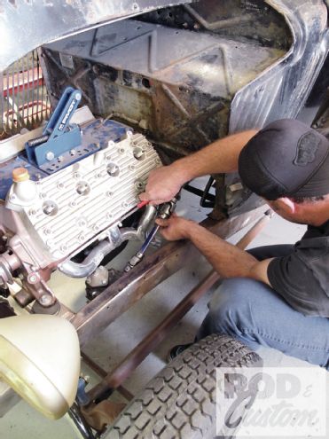
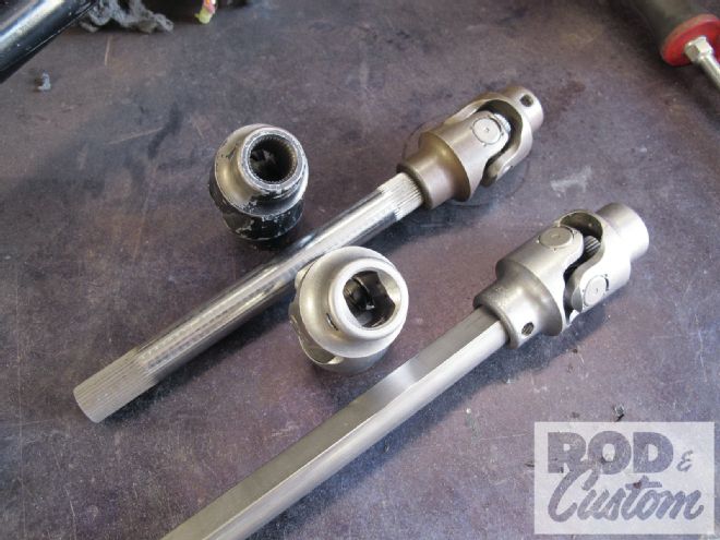
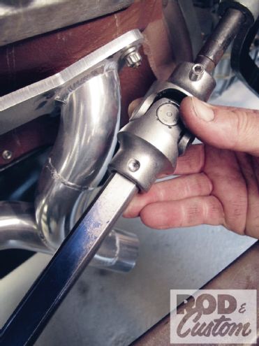
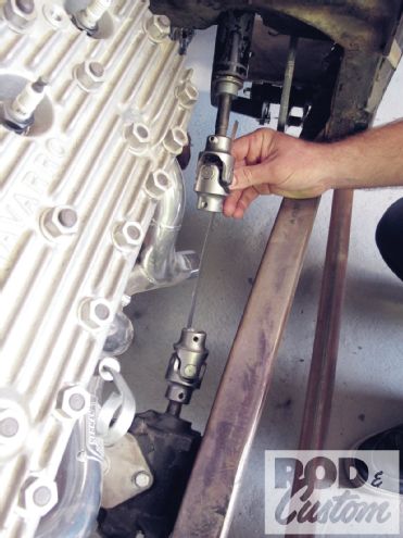 7. With the joints sorted out, the only remaining linking factor was to measure, cut, and install the intermediate (DD) shaft. Note White’s holding the upper joint in place to also illustrate why a standard coupler (nonadjustable) wasn’t used: it’s not a straight shot from column to box. Also note that, with the column secured using a lower mount to the floorboard, a support bearing is not necessary.
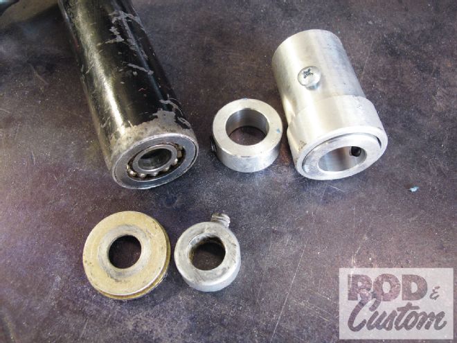 8. When it comes to using early "fixed" columns, securing the shaft is easy: CPP’s Column Saver (right). I’ve taken many 1930s-50s Ford and Chevy columns, once cut free from their original gear boxes, machined the free shafts down to accept a DD joint, and secured the shaft to the column tube with a CPP kit. That’s not the case here—at least not yet—as the previous modification included a lower bearing (left).
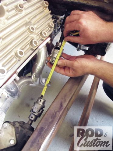
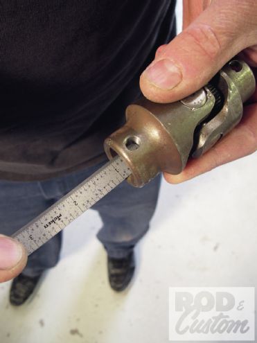 9. Measuring for the DD shaft ensued—first with the U-joints set in the respective positions when mounted.
 10. Then for total accurate length after factoring in the exact amount of protrusion into each joint half.
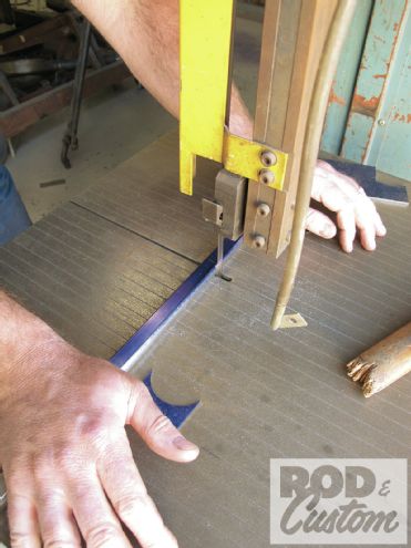 11. Once the shaft was initially cut to length, the linkage was mocked up to determine precise fit.
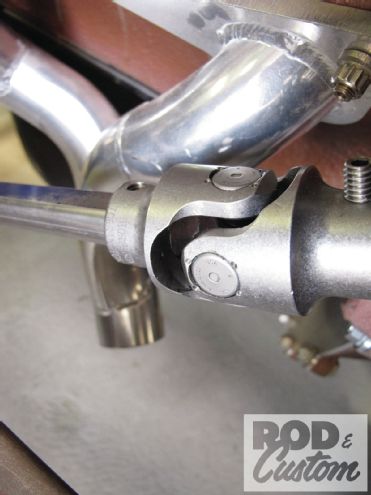 12. Note the end of the shaft is flush with the splined insert of the U-joint (arrow); this is necessary to avoid any binding during steering operation.
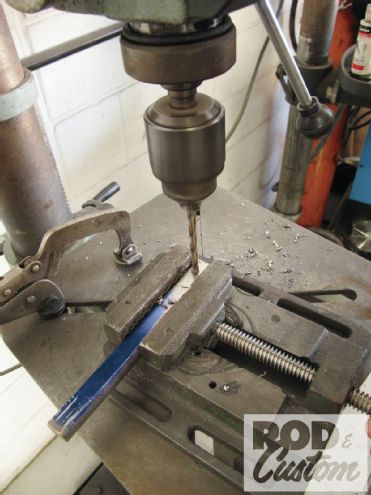 13. The shaft setup is not quite complete until a means of added security is put in effect. Recesses for the Allen setscrews are drilled into the DD shaft (on both ends; the indent in the output shafts will be used at the column/box) as shown.
 14. The shaft setup is not quite complete until a means of added security is put in effect. Recesses for the Allen setscrews are drilled into the DD shaft (on both ends; the indent in the output shafts will be used at the column/box) as shown.
 15. We'd already centered the box in the previous steering installment; same for the steering wheel. With a keyed shaft (as opposed to splined), getting the steering wheel straight is a 50-50 shot...with a three-spoke wheel such as the banjo, forget about it! It had to be right-on before moving on.
 16. Steering wheel lined up, the shaft was united with the U-joints...
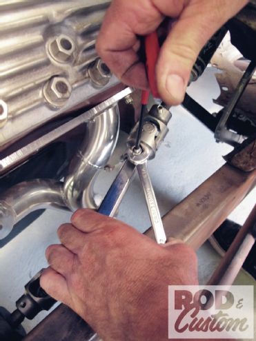 17. ...pinned in place with setscrews, and...
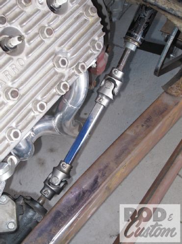 18. ...steering linkage done. As was the case with the steering column, our mock-up Hedman Flathead header looks like it’s going to make the cut, as it clears the steering (or is that the other way around?) perfectly, with room to spare. Once some floor work is complete, we’ll fashion up a formal collar to secure the lower portion of the steering column.
System Design Often the steering system is designed late in the building process. We recommend that the steering be mocked up at the time the engine and exhaust components are installed. Positioning of the column, shafts, and U-joints, with respect to the engine, exhaust, and steering box early on can help in selecting the correct parts. With our wide selection of U-joints, shafts, and vibration reducers, any system can be designed or modified to result in a car that is not only safe, but a pleasure to drive. Keeping a system simple is the best course, but even a system with up to 10 U-joints can be designed as long as the proper phasing and supports are used.">
18. ...steering linkage done. As was the case with the steering column, our mock-up Hedman Flathead header looks like it’s going to make the cut, as it clears the steering (or is that the other way around?) perfectly, with room to spare. Once some floor work is complete, we’ll fashion up a formal collar to secure the lower portion of the steering column.
System Design Often the steering system is designed late in the building process. We recommend that the steering be mocked up at the time the engine and exhaust components are installed. Positioning of the column, shafts, and U-joints, with respect to the engine, exhaust, and steering box early on can help in selecting the correct parts. With our wide selection of U-joints, shafts, and vibration reducers, any system can be designed or modified to result in a car that is not only safe, but a pleasure to drive. Keeping a system simple is the best course, but even a system with up to 10 U-joints can be designed as long as the proper phasing and supports are used.">
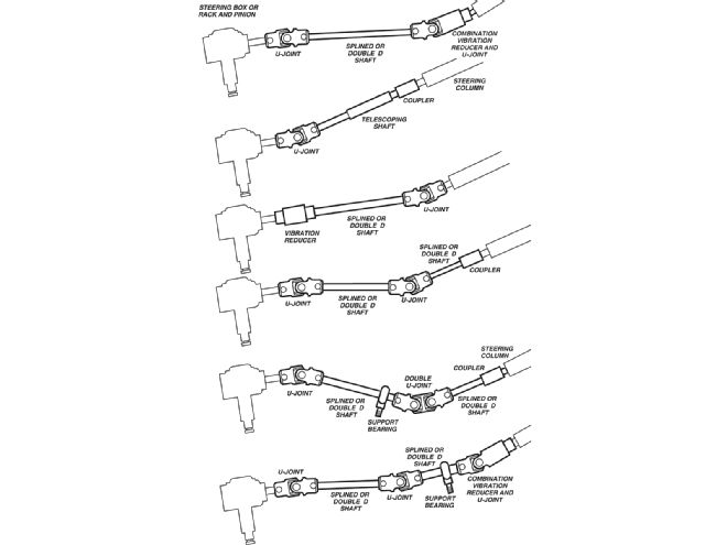 19. <strong>System Design<strong> Often the steering system is designed late in the building process. We recommend that the steering be mocked up at the time the engine and exhaust components are installed. Positioning of the column, shafts, and U-joints, with respect to the engine, exhaust, and steering box early on can help in selecting the correct parts. With our wide selection of U-joints, shafts, and vibration reducers, any system can be designed or modified to result in a car that is not only safe, but a pleasure to drive. Keeping a system simple is the best course, but even a system with up to 10 U-joints can be designed as long as the proper phasing and supports are used.</strong></strong>
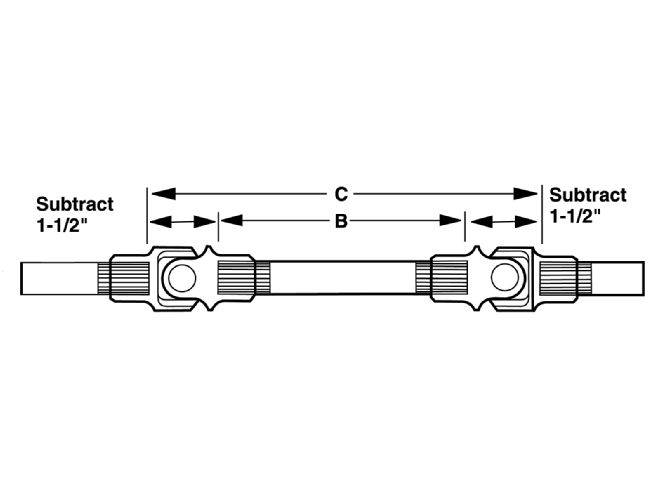
Steering Joints Determine splined shaft length with two U-joints: 1. Measure the distance from the end of the column to the box/rack (Dimension C). 2. Subtract 3 inches from this measurement. 3. Order the next even size shaft (Dimension B).">
20. <strong>Steering Joints</strong> Determine splined shaft length with two U-joints: 1. Measure the distance from the end of the column to the box/rack (Dimension C). 2. Subtract 3 inches from this measurement. 3. Order the next even size shaft (Dimension B).
U-Joint Angles of Operation The Borgeson needle bearing U-joints will operate smoothly up to 35 degrees. The double needle bearing U-joints will operate smoothly up to 70 degrees. The U-joints must not be altered in any way. Pin and block system U-joints will operate at 30 degrees smoothly.">
19. <strong>System Design<strong> Often the steering system is designed late in the building process. We recommend that the steering be mocked up at the time the engine and exhaust components are installed. Positioning of the column, shafts, and U-joints, with respect to the engine, exhaust, and steering box early on can help in selecting the correct parts. With our wide selection of U-joints, shafts, and vibration reducers, any system can be designed or modified to result in a car that is not only safe, but a pleasure to drive. Keeping a system simple is the best course, but even a system with up to 10 U-joints can be designed as long as the proper phasing and supports are used.</strong></strong>
Steering Joints Determine splined shaft length with two U-joints: 1. Measure the distance from the end of the column to the box/rack (Dimension C). 2. Subtract 3 inches from this measurement. 3. Order the next even size shaft (Dimension B).">
20. <strong>Steering Joints</strong> Determine splined shaft length with two U-joints: 1. Measure the distance from the end of the column to the box/rack (Dimension C). 2. Subtract 3 inches from this measurement. 3. Order the next even size shaft (Dimension B).
U-Joint Angles of Operation The Borgeson needle bearing U-joints will operate smoothly up to 35 degrees. The double needle bearing U-joints will operate smoothly up to 70 degrees. The U-joints must not be altered in any way. Pin and block system U-joints will operate at 30 degrees smoothly.">
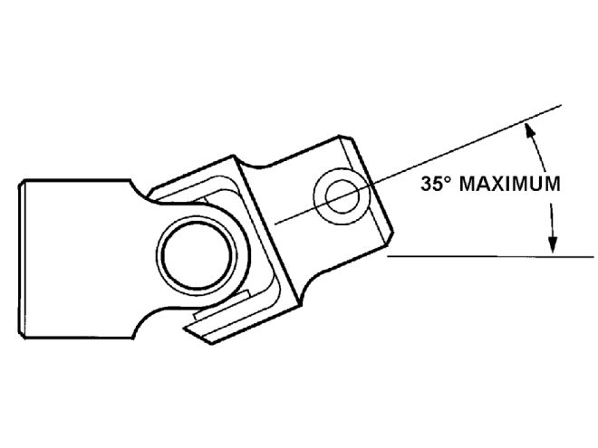 21. <strong>U-Joint Angles of Operation</strong> The Borgeson needle bearing U-joints will operate smoothly up to 35 degrees. The double needle bearing U-joints will operate smoothly up to 70 degrees. The U-joints must not be altered in any way. Pin and block system U-joints will operate at 30 degrees smoothly.