
Sometimes a simple change to your hot rod is all it takes to enhance its performance. By increasing airflow a properly designed fan shroud not only improves the efficiency of your engine, it can also significantly lower its operating temperature. This is especially important when hitting the road during the summer months where weather conditions and sluggish traffic can cause your temp gauge to increase in a flash. Ray Bartlett and his team at The Hot Rod Garage in Denton, Maryland, not only have a reputation for building wicked hot rods, they are also well known for laying down the miles on cross-country hauls where their cars are put to the test through all sorts of operating conditions where coolant temperature plays an important role. On a recent visit to the shop we met up with Dean Alexander who was preparing to fabricate a custom fan shroud for a ’34 Ford pickup.
With the truck being set up to run a 327ci Chevy V-8, his first order of business was to address how to effectively run a 15-inch mechanical fan. In stock form the engine’s water pump is mounted far too low for the fan to be efficient. To overcome this issue he installed a cast aluminum water pump riser by Zip’s, which placed the water pump and mechanical fan 5 inches higher at the front of the engine. To complete the update, he incorporated a water pump from a 250ci Chevy to the equation. With the fan placement issues resolved, it was time to begin measuring for the dimensions of the fan shroud. Accurate measurements are crucial in keeping the overall form of the shroud nice and tight to the radiator as well as keep the unit streamlined. Alexander obtained measurements from four main points on the radiator, which included the bottom of the top tank to the bottom of the radiator core, radiator width, the water pump center pin to the radiator fins, and the layback of the radiator. In obtaining the radiator layback dimension details, the water pump center pin was used as an intersect point from both the bottom of the top tank and bottom tank. For light weight and strength 0.080 6061-T6 aluminum was selected for construction of the shroud. Alexander transferred all of the dimensions to a fresh sheet of aluminum using a black marker and proceeded onto the fabrication process by first trimming all excess away using a Pexto Model 152-J metal shear. He followed by using an MSC metal notcher to remove the bottom corner sections to allow for the upcoming bends to the sides and bottom of the shroud.
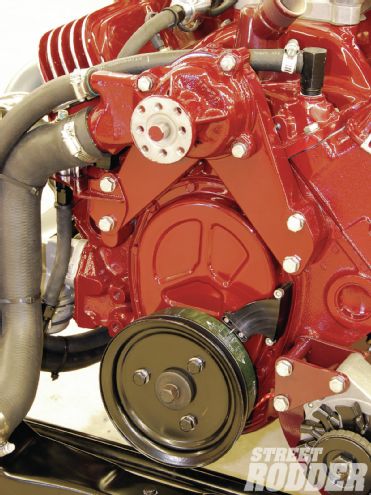 A water pump riser housing from Zip’s was added to raise the pump and mechanical fan 5 inches. A water pump from a 250ci Chevy six was then bolted on to complete the combination.
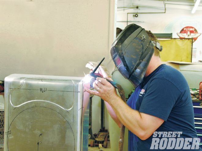
When locating the opening for the 15-inch flex fan, Alexander took into consideration an allowance of 3/4 inch for engine movement in keeping the gap between the fan and the shroud tight. He measured from the bottom of the top radiator tank to the water pump center pin 8-5/8 inches and marked for a pilot hole, which he drilled out with a 1/8-inch drill bit. From this pilot hole, he then measured 15-3/4 inches around with a ruler to complete the circle opening for the fan. Since the bottom of the fan shroud would be easily seen in the engine bay, a bit of design detail was added to infuse a bit of sex appeal to the otherwise blank area. Using a Mittler Brothers 4-inch high-throat power drive bead roller, a step bead was completed adjacent to the lower radiator hose outlet area. To work the 90-degree vertical bends into place with a graceful 1-1/2-inch radius a National finger break was used incorporating a custom roller fabricated by Alexander for the job. Many times in order to obtain a certain look a builder must fabricate one-off tools to do the job. Such was the case with the homespun dolly fashioned from a section of steel pipe and some flat steel stock, which Alexander whipped up to work a 1-1/2-inch radius into the bottom of the fan shroud. With a combination of mallets and body hammers he was able to work the aluminum to match the exact radius of the side panels. Once all of the necessary hammering and trimming was complete the first area checked with a T-square to make sure everything was even and then preceded to TIG-weld the bottom seams together using a Miller TIG welder. With the welding complete, the corners were cleaned up and ground smooth using an air-driven DA sander topped with 80-grit and finished by hand with 400-grit for a nice smooth surface. Finally the sides of the shroud were trimmed to allow for the 1-1/4-inch layback of the radiator while also marking for the mounting points of the shroud to the radiator sides at 3 inches and 17 inches from the top of the bottom tank upward on each side. Alexander (while wearing safety glasses) used a reciprocating high-speed air saw to masterfully trim the sides of the shroud as well as the fan opening while the unit was securely fastened in a bench vise. He then drilled out the mounting holes for the shroud sides using a 3/16-inch drill bit. The job was completed by deburring all of the trimmed surfaces with an air-driven angle grinder topped with a 50-grit disc followed by a 180-grit disc. To complete the shroud, the unit was sent off to the powdercoater to have a tasty black wrinkle finish applied. The completed unit not only looks bitchin’ installed in place, but will also enhance the airflow to lower the overall operating temperature of the engine’s cooling system while maintaining a neat traditional look.
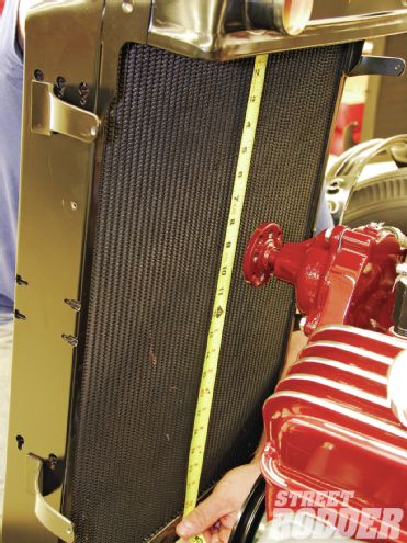 It’s important to gather the precise measurements needed for the construction of the fan shroud starting with bottom of the top tank to the bottom of the radiator core, which in this application was 22-1/4 inches.
With a mallet, Alexander started the initial 90-degree bend to the bottom of the shroud.
Following with a body hammer, the graceful curve to the bottom of the shroud began to take form when being worked with the custom-made jig as well as other dollies.