Certain design elements become signature when building a hot rod. From proper chassis dynamics and stance, to engine and rearend combinations, nothing speaks louder than a cowl steering setup. The team at the Rolling Bones Hot Rod Shop in Greenfield Center, New York, have incorporated one of its many influences by adapting Schroeder Racing Products steering assemblies into their cars.
Prior to getting started, Matt Schmidt obtained a number of precise measurements since the steering units are prepared by Schroeder for the customer's needs. This included a measurement for the steering shaft as well as the length of the sector shaft from the driver side of the cowl inboard to where the unit would be centered for the driver. Each measurement can be ordered in 1-inch increments with standard sizes for the steering shaft from 6-15 inches and sector shaft between 8-15 inches. The final measurement was for the support tube on the right side of the steering unit, which can be ordered in any length. With a number of steering assemblies available for different applications a decision is needed to best suit your build. Here, the team selected the Sprint & Midget steering unit with a steering ratio of 8:1. Schroeder also offers the option of a 6:1 ratio or their new reduced ratio worm-and-sector steering with a ratio of 16:1.
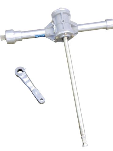 Rolling Bones contacted Schroeder Racing Products in Burbank, California, for one of their Sprint & Midget steering assemblies with an 8:1 steering ratio. The Ford-style Pitman arm is plenty tough and is constructed of 4130 steel.
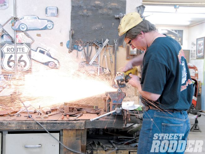
There are many different ways to brace and mount the steering assembly. The main concern is that the unit is properly anchored and rock solid. The Rolling Bones installation utilizes three mounting points for a clean and uncluttered look. Starting with a 1/8-inch steel plate, Schmidt cut the bases for the cowl brace and the lower firewall brace from established templates using a Hypertherm Powermax 350 plasma cutter. (Remember to always wear safety eye wear.) Once completed, each was cleaned up and deburred before continuing to the next step.
For the firewall mount, Schmidt proceeded with the base plate to the interior and mocked the plate into position. This helped determine the amount of contour it would need to bolt up to the firewall as well as any final trimming. Using a vise and steel hammer, the contour was laid into place and final trimming was done with a plasma cutter. With this portion completed, Schmidt proceeded to MIG weld a 3/4-inch steel block plate into place, which would act as an anchor for the right side of the steering assembly when combined with a top brace clamp. Moving on, Schmidt focused on the cowl brace. After measuring the baseplate, he added two 90-degree bends that would act as an anchor point where the front of the cowl meets the firewall.
Next it was time to establish the mounting point for the sector shaft tube with another prepared template. Schmidt used his plasma cutter to make the cut and then proceeded to MIG weld a 3/4-inch steel block plate into place that would be used as the anchor point for the tube when combined with a brace clamp. With the cowl brace clamped into place, Schmidt proceeded to take measurements while using a mock-up steering support tube to assist with the final placement of the steering assembly. To ensure correct positioning, Schmidt confirmed measurements from both the frame and body, guaranteeing a perpendicular position.
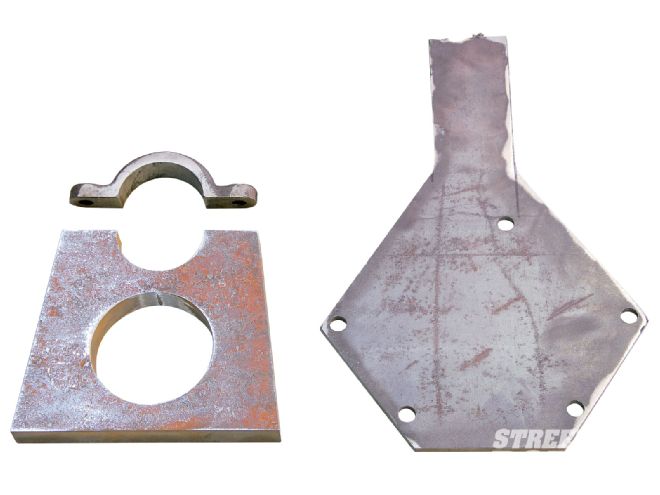 To support the righthand side of the steering assembly, an 1/8-inch steel plate was designed to utilize factory Ford mounting points on the firewall. This is combined with a 3/4-inch steel block lower firewall brace to support the steering assembly mounting tube. The completed unit is ready for installation.
Once the dimensions were set, Schmidt established where the cowl needed to be opened up for access of the sector shaft and Pitman arm. For this he used a long punch (which was incorporated into the mock-up tube) to add a dimple (with one stroke of a hammer) to the cowl indicating the center of the opening needed. From outside the car, he used a 3-inch holesaw to create the access for the steering unit's sector shaft and Pitman arm. Once the hole was completed, he deburred the opening to clear it of any sharp edges.
At this time Schmidt set sight on fabricating the final mounting point brace. Using 1x2-inch mild steel flat stock, he created a support that would tie in the lower firewall to the top of the chassis 'rails to deter any potential flexing of the steering assembly. The brace also functions as the perfect anchor for the floorboards and transmission cover. With all of the fabrication completed for the bracing, each part was fully prepped for final molding, paint, and detail.
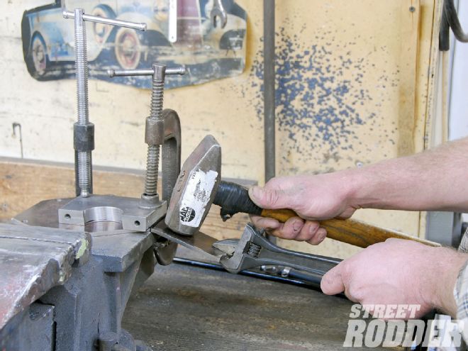 Once the 1/8-inch steel firewall brace base was cut, it's mounted in a vise and bent to fit the firewall contour.
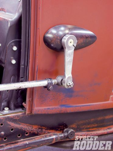
With all of the braces mounted, the Schroeder steering unit was lowered into place and left slightly loose to allow for any final adjustments. Outside the car, Schmidt installed one of Rolling Bones' signature steering blisters, reminiscent of those used in early lakes-style racing. Schroeder Racing Products offers a number of different Pitman arms to suit various applications. Here, Rolling Bones opted for Schroeder Model ST1-Ford with its vintage Ford styling. Schmidt installed the Pitman arm and made note of the trimming in length, which would be required for the drag link to be parallel with the Pitman arm. This trimming also required the unit be sent to the local machine shop to have a new tapered tie-rod end hole added. With the Pitman arm back from the machine shop, Matt completed the fitting and secured the Pitman arm into place with a 5/16 Allen wrench followed by the tie-rod end and drag link.
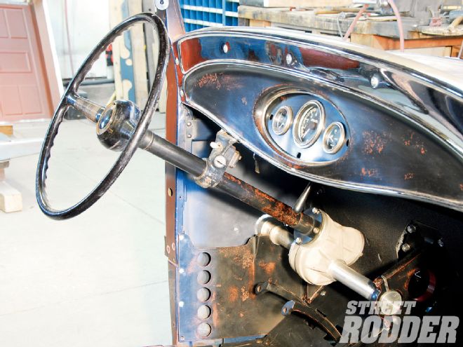
With only a few steps left, attention was again focused inside the car for the installation of the gauge tunnel, dash, and a custom bridge (fabricated form 1/8-inch steel plate), which supports the dash, steering column, steering box, and column drop for added strength. An original '40 Ford steering column was shortened to fit and was anchored to the Schroeder unit by way of a custom fabricated circular sleeve that's mounted directly to the steering box (again for additional strength). Supported by an original early Ford column drop and crowned with a vintage '40 Ford steering wheel the installation looks downright bitchin'. Reading like another chapter from the book of gow, the installation has proved flawless for thousands of miles as the team from Rolling Bones canvass the country in their wicked hot rods.
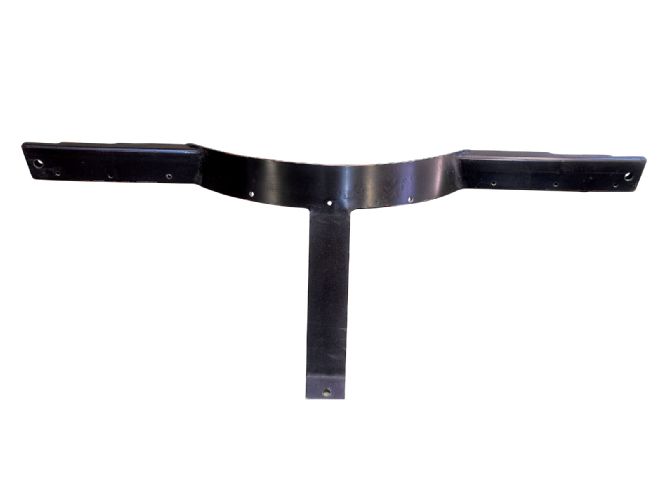 This support, constructed from 1x2-inch mild steel, will brace the lower firewall and tie it into the top 'rails of the chassis to avoid flexing. The unit also acts as a brace for the floorboards and transmission cover.