A few issues back we ran an article in Circle Track on modifying the Rochester four-barrel carburetor for maximum performance in circle track racing. We went to Sean Murphy, owner of Sean Murphy Induction (SMI), as a resource, and he provided a wealth of information on everything from choosing the right version of the venerable Rochester to tuning tips.
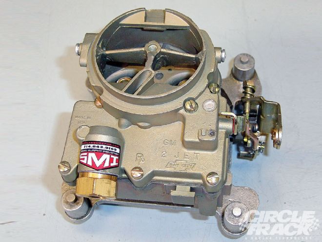
 The two-barrel Rochester 2G wasn't exactly designed with racing in mind, but with the right modifications it works very well in several entry-level classes.
That article was so well received, we decided to go right back to the well. What we realized the last time around is that we left out all the Bomber class and IMCA racers who are required by the rules to run a two-barrel original-equipment carburetor-which almost always means the Rochester 2G. Unfortunately, because the designs are so different, most of the tips Murphy provided for the 4G simply won't work with the 2G. Instead, this carburetor requires an entirely new approach.
"It's different," Murphy says, "but it's also a much simpler carburetor. It's very versatile and it's quite durable. If you want to start working on and modifying your own carburetors, the 2G isn't a bad place to start."
According to Murphy, Rochester began producing its two-barrel carburetor in 1954. It went into mostly General Motors automobiles and trucks. Large-scale production lasted until 1979, meaning the Rochester 2G is still plentiful and readily available for racers looking for hardware. There isn't much in the way of rebuild kits available, but Murphy says it's usually easier and cheaper to buy a second carburetor and strip it for parts anyway.
Over the years, SMI has built a winning program developing Rochester 2G carbs for entry-level racing classes, making the company one of the leading builders of these carbs. Following are Murphy's tips in his own words for getting the most power possible from the venerable 2G.
Carb Sizes and CFM
Even though the 2G ended major production in 1979, it still lived on a little further in boats, heavy equipment, and even school buses. In the heavy-equipment applications, some of the carburetors had governors on them even so those can actually be more desirable because they are the biggest ones.
The cfm (cubic feet per minute-a measure of how much air the carburetor can flow) on the Rochester 2G ranges from about 225 cfm in the smallest applications up to what Rochester calls a 435 cfm. But the 435 is actually commonly referred to as a 500-cfm carb in circle track racing because it has the same diameter venturi bore and throttle bore sizes as the Holley 4412, which is a 500-cfm carb. Rochester just ran a different test on the flow bench to rate its carbs than Holley did, but generally, if you flow them both on the same bench, each will flow right around 500 cfm.
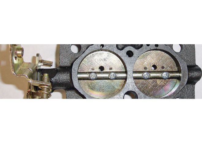
Throttle Plates and the Idle Mixture
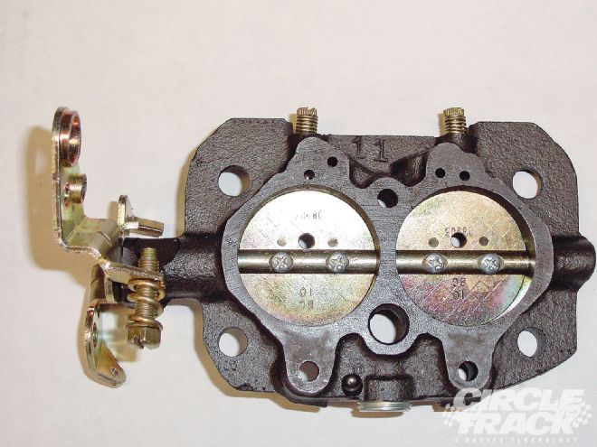
One of the few things that basically works the same with these carburetors as the four-barrel Rochesters is the throttle blades. Photo 1 shows the throat holes in the throttle plates, which are relatively large. In these photos the holes are 0.180-inch. It doesn't matter where on the plates you put the holes but their size does matter.
 <strong>1</strong>
The purpose of the holes is to allow enough air through the carburetor and into the engine so that it idles correctly without having to open the butterflies and expose the transition slots. And with a race engine, you are almost always running a larger camshaft which requires more air, so those holes will have to be enlarged. The transition slot is barely visible in this photo, which is what you want. You can see it on the lefthand side in the throttle bore at the 12 o'clock position.
As you are drilling out the holes, be careful to only make it larger in small steps. This is true with a lot of the changes you make on the carburetor-since a race motor will want more air and fuel than a street motor, just about everything you do will be to make the channels and openings larger. But it's always easier to make a hole bigger than it is smaller. In fact, in some cases, like with the throttle blades, it can be practically impossible to make the holes smaller. If you wind up making the holes too large your only option will be to go out and find new throttle blades to replace the ones you've ruined. So, try to sneak up on those throat holes until they are just the right size.
Main Body Sizes
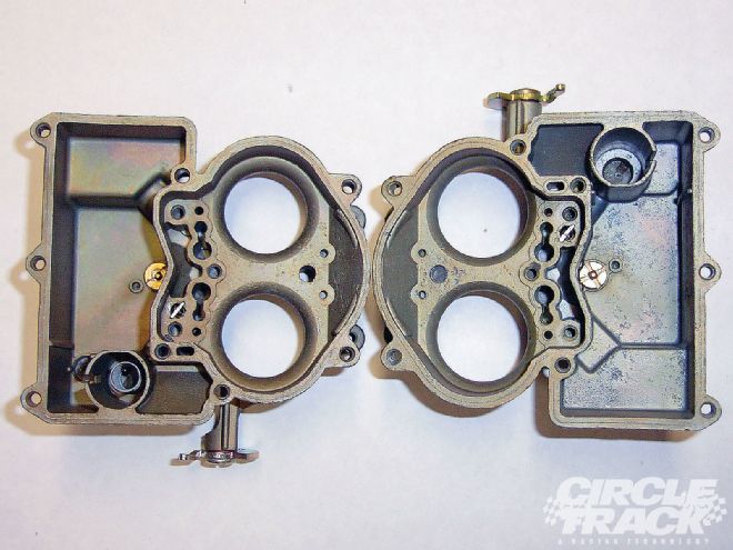
There are two basic sizes that are used in circle track racing. The two sizes came from the factory, and you can still find either fairly easily. The smaller carburetor is on the left in Photo 2, and you can easily tell by looking at the size of the center divider between the venturis. That unit on the left is what we refer to as a 390-cfm, and the venturis are 1 1/4 inches in diameter. The one on the right is for a 500-cfm carb and the venturis are larger at 1 3/8 inches.
 <strong>2</strong>
The problem is, the 1 3/8-inch venturis are better for racing applications because they flow more air, but they are also going to be difficult to find. So we've figured out how to machine the smaller ones out to the 1 3/8 size because they were the more popular size and are still easier to find.
If you are hunting for a 2G carburetor and want to figure out which one of the two you are looking at, there is actually a very easy method. Rochester produced the 2G with a ton of different part numbers, so it can be really confusing to try to check the part number on some random unit and try to figure out what you are looking at.
Instead, you can take a 1-inch open-end wrench and use that. On the 1 3/8 unit the open end of the wrench will just barely fit over the divider between the two venturis. But on the 1 1/4 unit, the divider is larger and the wrench won't fit over it. It's a quick and easy go/no-go tool to figure out what you've got.
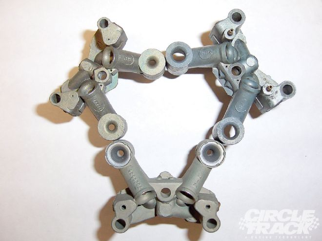
Emulsion Hole Patterns
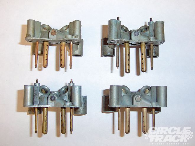
Photo 3 shows the different types of emulsion hole patterns that are available. If you look at the big tubes in the brass tubes in the middle of the clusters, you can see that there are both different size holes and different numbers of holes. Unlike the size of the venturis, where you almost always want the larger size, here one style isn't necessarily better than another. It's more of a situation where some fit certain applications better than others. You just have to figure out which work best for what you are trying to do.
 <strong>3</strong>
Occasionally, we'll modify these hole patterns further to get what we're looking for. Unfortunately, this is one area where I can't tell you one way that works best. It requires a lot of experience to learn and understand what works best for each situation, and the differences can be small.
The emulsion holes aren't a tuning tool. In other words, you won't be changing them out depending on what track you are running or if conditions change. What we usually do is pick the best one for the application and then set it up so that the racer only has to change the jet to get the correct fuel curve.
If you look at the cluster on the bottom left, you will see that it has four emulsion holes, and the bottom two are larger than the top two. Sometimes we will enlarge all four holes. Sometimes we will only enlarge a couple. And sometimes we will add a couple more holes and enlarge those. So it's basically the number and size of the holes that we will work with to custom tune the carburetor to the application.
The smaller tubes on the outside edges of the clusters are what we call the idle pickup tube. Those are basically the jets for the idle circuit. And you can see in all but one they have a little extended tip on the bottom that's a smaller diameter than the rest of the tube. That is the area where the restriction is, so that's basically the jet orifice, if you will.
As a general rule, the larger the cam, the larger that tube needs to be. And you can see on the one on the bottom righthand side, those extensions are gone. That's because it's going to be used in a car with a very aggressive camshaft. With a real big cam, it wants all the fuel you can get down to it, so sometimes you just have to open up that tube as much as you can.
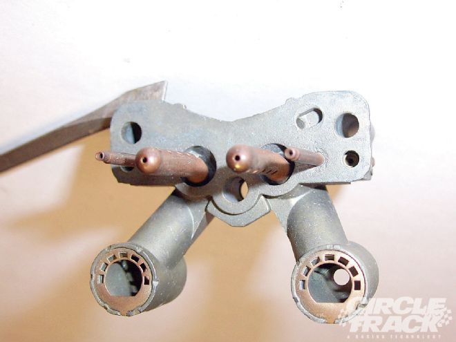
The Cluster Center Hole
In Photo 4 we are still looking at the clusters, just at a different angle. Now we're showing the different center hole sizes that can be found in the cluster. The one on the top right is what everybody considers the most desirable. It has a 1/4-inch diameter booster which is good for total airflow but not necessarily as good for atomization of the fuel or even the signal strength in the venturi. So you may have to work in other areas of the carb to overcome those problems. Also, that hole size is by far not the most common, so it isn't always easy to find.
 <strong>4</strong>
The center hole size that is the most common is in the cluster on the bottom of the photo. So, what we've done is figure out a way to modify that unit to the 1/4-inch hole because it simply is not worth the time and effort to go chasing after the other cluster. I'd say 90 percent of the 2Gs you will find will have a cluster like the one in the bottom of the photo.
Also notice the cluster in the top right. At the top there are two holes adjacent to and above the mounting screw holes. The one on the upper right has some small brass restrictors in those holes. That's the idle air bleed, and it will have an effect on your idle mixture as well. As we've talked about earlier, the down tube kind of acts like the jet, and that's the air bleed for that. The way it basically works is the idle tube comes up just to the left of that and then it mixes with the air for the idle bleed, and then it's transferred down through the idle discharge in the baseplate. So that's another tuning aid when using larger camshafts. You can alter the size of the air bleed to modify the fuel curve on the idle circuit.
The Channel Restriction Orifice
This one can be a little bit difficult to see, but it is still important. We're still working with the cluster as before. The fuel comes up the idle tube and then mixes with the air in the air bleed. And then in Photo 5, you can see the arrow pointing to the hole that it comes down. The problem is there's actually a restriction in there. It's a little brass restrictor, and that one is critical because it has a big effect on the transition slot. Basically, it meters the total amount of air and fuel mixed together that the idle circuit will get. That is called the channel restriction orifice. Generally, we will drill that restriction out to between 0.055 and 0.063 depending on the situation.
 <strong>5</strong>
In this case, if you find that you've drilled it out too large it is possible to fix it. Just drill it on out further and insert a Holley air bleed.
By the way, while we are looking at the boosters in this photo, there is another booster design out there that's got a bit of a mythical reputation to it. That one's a bit famous because everyone wants one but so few have ever seen it. It's simply called the "Truck Booster" and it has really good signal strength and atomization properties. But it's very rare and very hard to find, it's really a piece of 2G trivia more than anything.
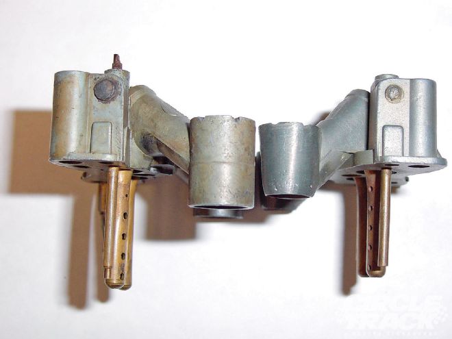
Booster Length
What you see in Photo 6 is something that we mainly do. That's a stock length booster on the left, and on the right is a booster that we've shortened and tapered. This modification can show some very significant gains in airflow, but you've got to check your rules to make sure it's legal or at least make sure you won't get caught. This is one of the best modifications you can make in terms of increasing performance because we're talking about gains in the range of 30 cfm.
 <strong>6</strong>
And there's another trick you can do to help the airflow even more. There is a gasket that sits underneath that piece. You can stack a couple gaskets under there and that picks the booster up out of the venturi which also increases airflow. I don't know if I should give that one away because I haven't seen any of our competitors doing that one yet, but there you go.
Modify the Throttle Shaft
There's another easy trick that can help you squeeze some more airflow out of the 2G carburetors. The throttle shaft, like you can see in Photo 7, is what's called a sandwich shaft. In other words, there are two slabs to the shaft and the throttle blade sits in between them.
 <strong>7</strong>
What you can do is cut off the top of the shaft and then mount the blade just to the bottom half of the shaft. And make sure to use a flat-head screw instead of the tapered screw like you see in the photo. That modification is usually good for an additional 10 cfm.
High Speed Air Bleeds
If you will look back to Photo 4, notice the two small holes on either side of the center mounting screw in the two top clusters. That is the high speed air bleed, and that is another thing you can use to tune the fuel curve besides the jets and the emulsion system.
The high-speed air bleed can be used to fine-tune the last quarter of the fuel curve. For example, let's say the motor looks good in the midrange from 4,000 to 6,000 rpm. The fuel curve is nice and on the dyno it's showing a 5.0 brake specific fuel consumption (BSFC) and 12.9 to 13 on the air/fuel ratio. But after six-grand, it starts going rich and you get mid fives on the BSFC and low twelves on the air/fuel. What you can do is open up the high-speed air bleed hole without changing the jet, and that will lean out the top of the fuel curve without ruining your midrange.
Again, this adjustment means taking a drill to the carburetor, so take it easy and be careful not to cut out too much at once.
Now look at the cluster at the bottom of that photo. You will see that the high-speed air bleed holes appear to be missing. They aren't, instead they are actually in the face of that area instead of on top. In other words, they are 90 degrees opposed to where the air bleed holes are on the other two. Having the high-speed air bleed holes on top works better, so you either want to avoid using one with the holes in the face or modify them. We actually drill out new holes into the top and block off the holes in the face with lead rather than use them that way.
Also, take a close look at the cluster on the top right. There are two holes that you can see in the nodules that stick out from the face area. You can also see them a little bit on the bottom one as well. Those are the accelerator pump discharge nozzles.
The discharge nozzles are also an area you can tune by opening up the holes. You might want to do this if you notice you are getting a stumble when coming up off the corner. That's essentially the equivalent of going to a bigger squirter on a Holley carburetor.
But to be honest with you, that's not usually necessary on a 2G because it's such a small, restrictive carburetor and is almost always maxed out on the racetrack. You don't need a lot of accelerator pump on the track because there is so much air flowing through the carburetor and you keep the engine at a high rpm on the track, so the main circuit gets activated very quickly. This means that there is usually little to no need for any pump shot once you are actually on the racetrack, because the air speed through the carburetor is so high since it's acting like a restrictor on the engine.
What you are trying to do when you are forced by the rules to run an undersized carburetor is deal with a situation where the air moving through the carburetor is at a far greater speed than the carb was ever designed to handle. When you are dealing with a four-barrel you are trying to encourage each circuit to respond more quickly and do its job better, but with the 2G you wind up trying to kill off some of the circuit's function because it's in a hyper mode, so to speak. The air speed is just too fast, so when working with these carbs, keep in mind that you are actually trying to slow things down in order to increase the quality of the state of the fuel when it gets to the engine.