A car's driving position is one of the first impressions it leaves on the driver, and it can make all the difference between an enjoyable drive and one that feels awkward. That's doubly true in aggressive driving situations where you need to feel confident and in control of the car or you'll never be able to extract the most you can out of its potential.
While most modern cars offer several options to tailor the driving position such as column height and steering wheel angle and seat height, inclination, and back rest angle, most muscle cars are pretty much set wherever the factory felt was a good shot down the middle for the masses. The result is a lot of less-than-ideal seating positions that you pretty much just have to get used to. But is there actually a correct driving position for everyone?
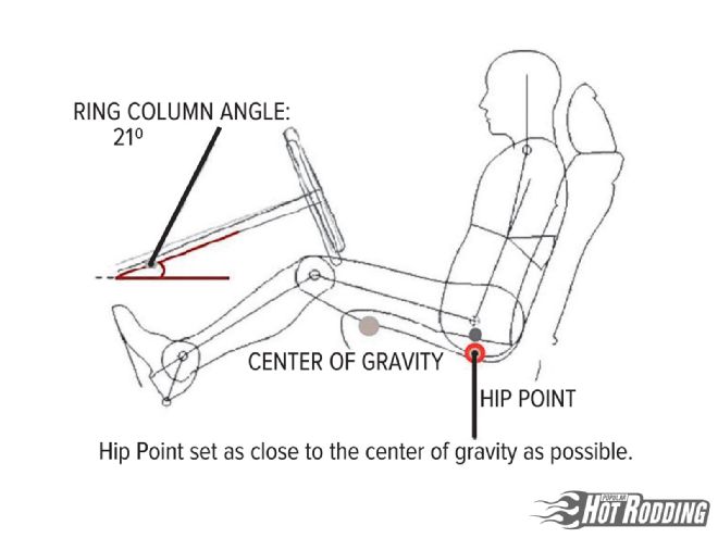
Turns out, there is a loose formula for driving position that is considered "ideal," and it's probably not much like your daily driving position. Assuming all variables are open, one key factor is getting your hips as low and as close to the center of gravity as possible without creating a forward visibility problem. You get two benefits here; your weight is lower which helps vehicle dynamics, and when properly belted down being closer to the vehicle's yaw, pitch, and roll axis will yield a better feel for what the car is doing during changes in speed or direction. Also, with your body tucked firmly against the back of the seat, you should be able to fully depress the brake and clutch pedals without fully extending your legs. With your shoulders against the seat back and your arms fully extended, the top of the steering wheel should meet your wrists. When gripping the wheel at the 9 and 3 o'clock position, there should be a 90 to 130 degree bend in the elbows. That's a good place to start; from there deviations will be mostly driver preference.
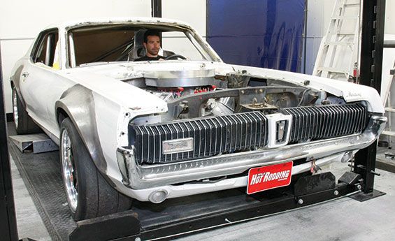
That's assuming all other things are stock; it gets quite a bit more complicated if you've been cutting. Since the Max Effort '67 Cougar engine position has been moved so far back that we need to build a new firewall, it's the right time for us to begin tackling the variety of factors that will contribute to reestablishing a good performance driving position. That means we've got to solve several problems simultaneously, including building a new firewall, and mounting a new pedal assembly and steering column since their positions will influence one another. Since they have close relations with Wilwood and a history of building excellent performing cars as well as a crew of talented metal shapers, we're back at JCG Restorations & Customs to get the first few critical points nailed down.
1.This is roughly the arrangement used by most professional drivers in race cars; note the hip height relative to the center of gravity of the car and the knees with pedals at full extension. The steering column angle will vary depending on driver preference and other considerations such as the vehicle type and cockpit layout.
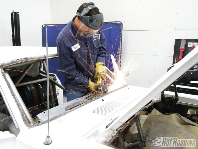
2. Before we can begin building or setting up anything, we've got some cutting to do; to get access to the location for the new firewall, which will dictate all the other placements, we need to remove the dash structure.
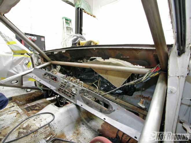
3. With the dash structure cut out we have a clear view of the cowl section of Max Effort so we can determine how far back from stock we'll need to position it, as well as figuring on how much room we need to weld in new mounting brackets.
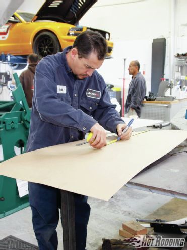
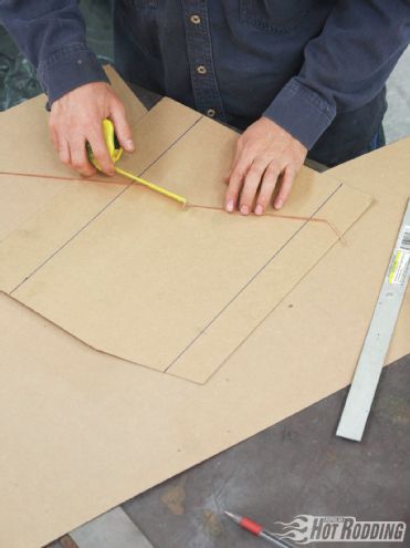
4. When fabricating new panels, a cardboard template is the first place to start. After taking some measurements, JCG lead fabricator Primo Valdovinos cut out a large piece that will be the template for a little more than 75 percent of the firewall. The section where the steering column passes through will be built separately since it requires more forming.
5. After finalizing the shape through test fitment in the car and transferring the dimensions onto sheetmetal, Primo used a bead roller to create some basic rectangular forms to add rigidity to the panel. He also used a special set of flaring dies to begin the bell of the transmission tunnel. (For more DIY details on bead rolling panels just like this one, see "Perfect Panels" in the Jan. '13 issue of PHR.)
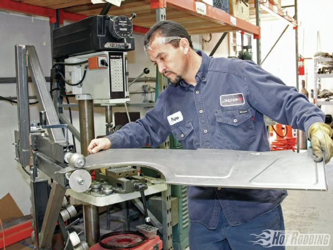
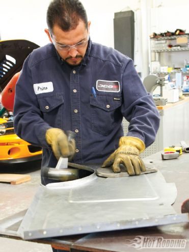
6. To exaggerate the flare further, Primo used a shaping hammer and a large flat dolly to tap the lip to almost 90 degrees from the firewall. This will create a shelf for attaching the tunnel later.
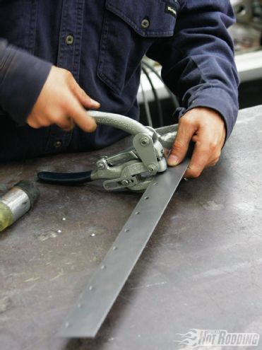
7. Repositioning the firewall further back also means we need to create new mounting points for the new firewall under the cowl. The sides and bottom of the wall will be straight, but the top needs to be more organically shaped to follow the cowl vent floor. Beginning with a flat strip of sheetmetal, Primo punches holes at regular intervals for some rosette welds.
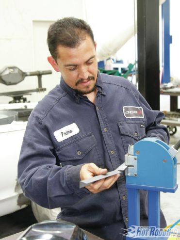
8. Using the shape of the firewall template as a reference, Primo then used the shrinker and stretcher to curve the sheetmetal to follow the shape of the floor of Max's cowl vent. If you're doing the work yourself, you can pick up a shrinker/stretcher combo tool kit from Eastwood for around $200 (PN 51088).
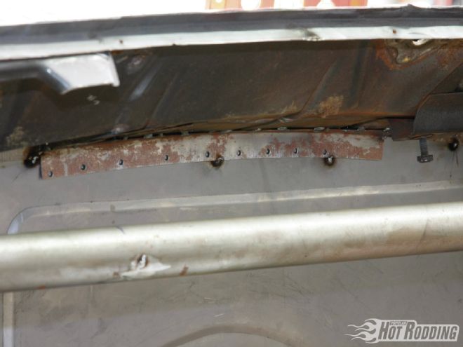
9. Welded into place on the cowl vent floor, we now have a strong bracket to attach the new firewall.
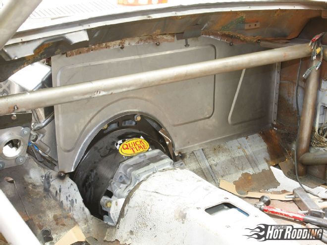
10. With the new firewall slid into place, this is what the front of Max's cockpit looks like.
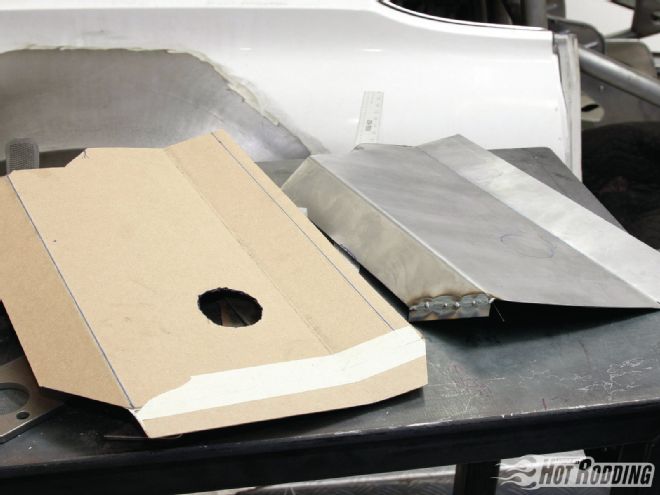
11. The section of the firewall the steering column passes through required a bit more shaping to put the column in the correct position. This will account for the extra space needed for mounting the pedal assembly under the dash and allowing full swing of the pedals. Primo used a piece of TIG welding rod to figure out what would fit and then transferred the bends to a cardboard template.
12. Once he was happy with the template's shape, he copied it onto sheetmetal. The hole represents the stock steering column position, which we used as a starting point.
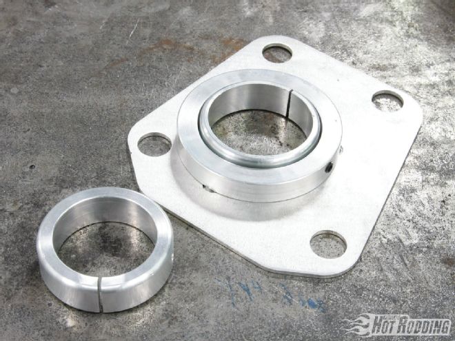
13. Rather than a stock-style column we'll be using one of Flaming River's 1.75-inch diameter motorsport columns (PN FR3306, $215.95 from Summit). The firewall mount provided with the column allows a good bit of adjustment, which will help us with fine-tuning the position and angle. These slick mounts also bolt right into stock Mustang and Cougar firewalls to adapt a Flaming River column to help you tailor your own car.
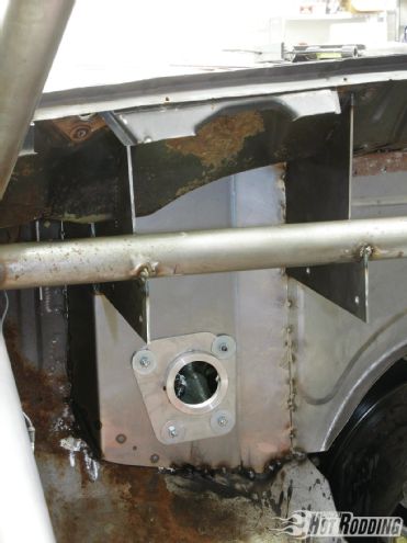
14. This is how the panel looked tacked into place with the mount bolted in. Also note the two heavy gauge steel panels hanging from the cowl floor and rollcage dash bar; these will be the mounting brackets for our pedal box and steering column.
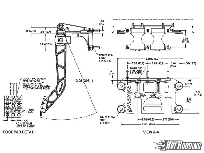
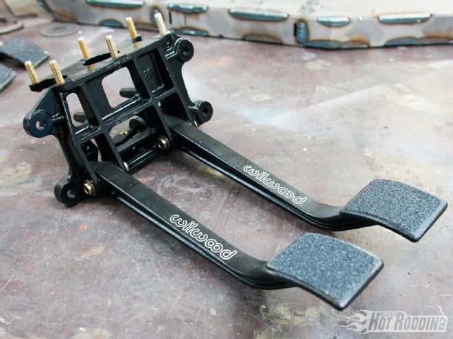
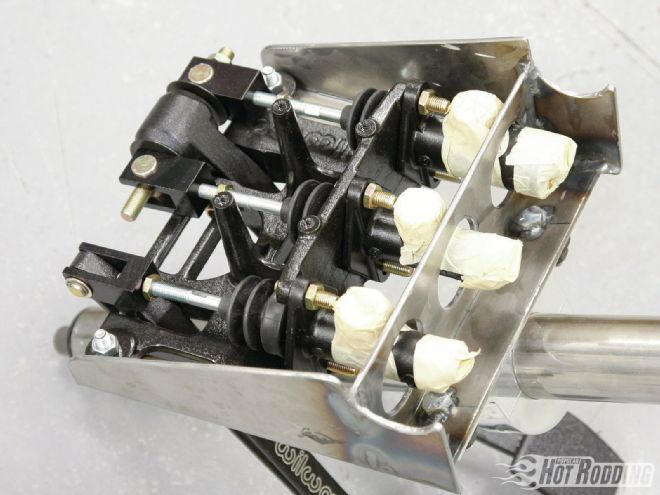
15. If you have the pedals you want to use on hand, it's easy enough to mock things up, but if you'd rather test before buying, Wilwood has tech docs with all pedal assembly dimensions and specs, including the all-critical pedal length and swing on their website. We chose Wilwood's reverse-mount brake and clutch pedal assembly (340-11299, $244.02).
16. We needed some fairly long pedals to account for the steering column position, plus it was determined that we needed to use a reverse mount to run the master cylinders under the dash. It's not the most ideal solution for ease of maintenance, but Primo devised a solution.
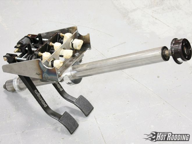
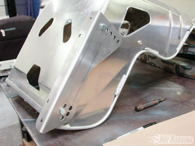
17. To make the master cylinders more easily serviceable, Primo built a box that the pedals and master cylinders mount within and that also provides the mounting point for the steering column. The whole assembly will slide between the brackets welded to the cowl floor and rollcage.
18. Our Wilwood master cylinders have a ¾-inch bore for the front brakes and clutch (PN 260-10372, $85.95 each), and a ⅞-inch bore for the rear brakes (PN 260-10374, $85.95 each). These master cylinders allow for either direct or remote mounting of the reservoirs; we'll need to mount them remotely.
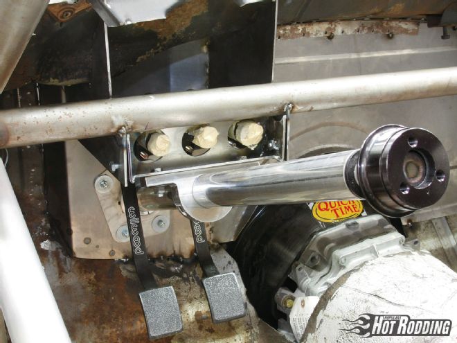
19. Bolted into place, this is what the final box looked like. Dropping the column and masters only requires removing six bolts. The holes where the front of the master cylinders pass through will aid in plumbing them.
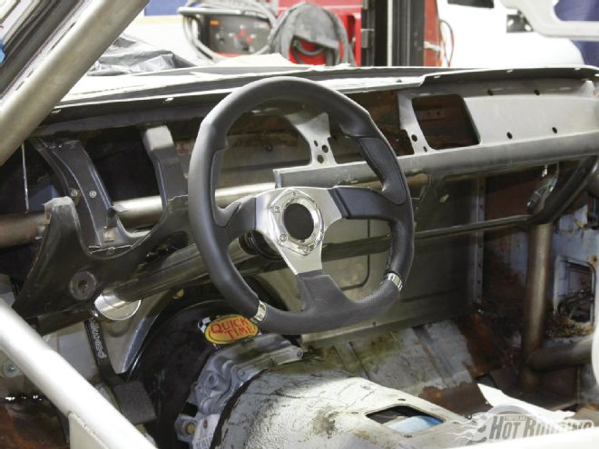
20. Once the final welding was done on the pedal box and firewall, Primo welded the dash structure back into place, and we popped on the Flaming River steering wheel. The column is perfectly centered in the original dash cutout, and we have plenty of room to raise or lower it if need be.
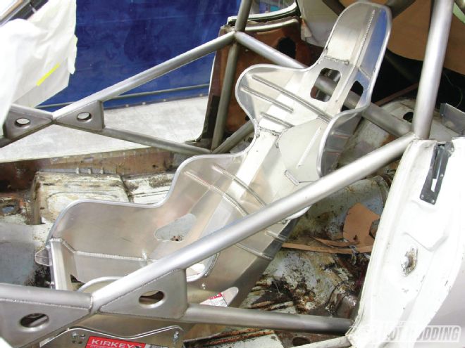
21. For our seating in Max we're going with Kirkey Racing Fabrication's intermediate road race seat. These seats are super light and rigid, and are available in four sizes: a 15-, 16-, 17-, and 18-inch width, all with a 15-degree layback ($259.95 from Summit). They've been staples in the racing world for years, and they're still very affordable.
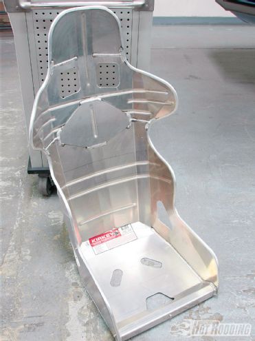
22. Most Kirkey seats require you to install your own brackets, but fortunately they allow for adjustment of the height and angle of the back to compensate for the shape of your floorboards.
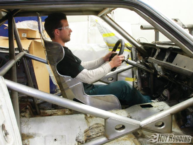
23. We'll admit we ran out of time to establish the final mounting solution for the Kirkeys, which is why it's leaning against the rollcage, but we did get the basic height and angle we wanted, which is the most critical consideration.
24. It felt good to sit behind the wheel of Max again, even if it'll be a while before we get to drive it. We have a good upright seating position and between 90 and 130 degrees of bend in the elbows with our hands on the wheel in the 9 and 3 o'clock position. Though we may go a little lower on the seating and column angle, it's not bad at all; we can fine-tune from here.