Oftentimes, it’s easiest to address problems with the path of least resistance. But what about when that problem is a firewall that prohibits the use of an HEI distributor cap in your small-block-equipped 1955-’57 Chevy? Many would recess that seemingly troublesome firewall, but it’s not the firewall’s fault. So, why not forgo the sheetmetal surgery altogether and simply move the engine forward? For the naysayers who throw in the “having to make new engine mounts” and the like, there is a simpler solution.
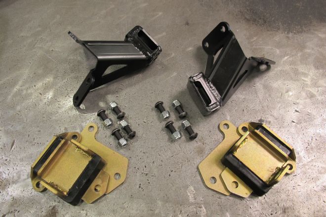
Classic Performance Products offers an engine mount kit that does the trick—their fabricated pedestals push a small-block forward 3/4-inch (while their Fit-Rite LS-series engine plate kits give you a full 3 inches of adjustability). Of course, that does leave you with having to similarly address the transmission mounting, but their adjustable trans crossmembers handle that rather well.
CPP’s 3/16-inch-thick steel pedestals come in both stock and forward-mount location options, and work with either standard rubber or polyurethane SBC mounts. Easing the installation factor, the pedestals are designed to initially locate off factory rivet holes in the front crossmember (requiring the removal of said rivets as well as drilling two additional holes). With the engine in or out of the vehicle, the job is quite simple and very straightforward, as we’re about to illustrate for you here.
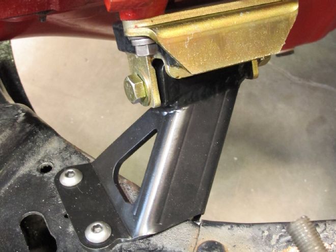
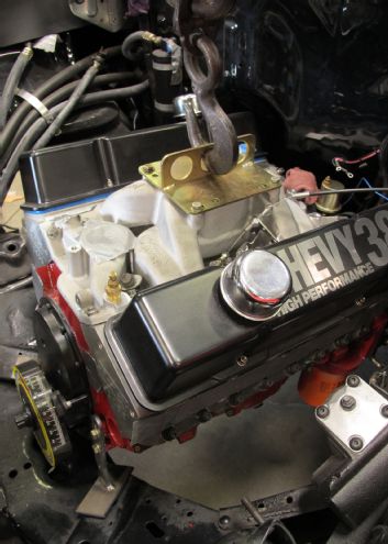
01. Fabricated out of 3/16-inch steel plate, CPP’s 1955-’57 Chevy pedestals locate a small-block V-8 3/4-inch forward (also available in stock location) and utilize standard rubber or upgraded poly engine mounts.
02. Our 1955 Bel Air had a side-mount conversion done at some point, but as you can see, the brackets were actually welded to the frame after being bolted in.
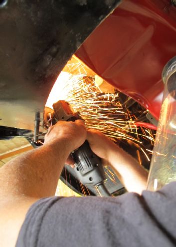
03. Nothing a little extra time with a cutoff wheel and grinder couldn’t take care of.
04. Prior to the old mounts being completely removed, the engine itself was supported with a cherry picker. For those performing the job with the vehicle on the ground, it might be better to remove the engine/trans altogether, if possible.
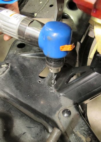
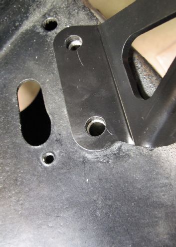
05. With the mounts out and the crossmember rivet heads ground flush with the framerail, the bodies of the rivets are drilled (3/8-inch bit) and subsequently punched out.
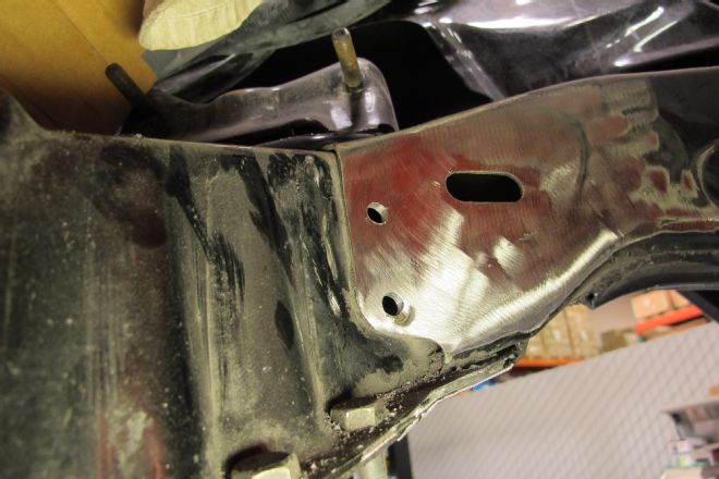
06. These holes locate the rear portion of the new pedestals.
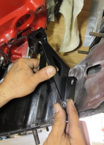
07. Verify the holes on the pedestals align with those in the frame—if slightly off, chase the frame holes with 25/64-inch drill bit.
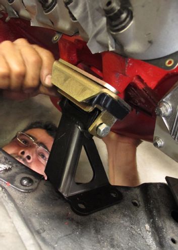
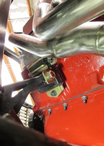
08-09. With the engine still supported securely, the engine mounts (with supplied plates) are test-fit to the engine.
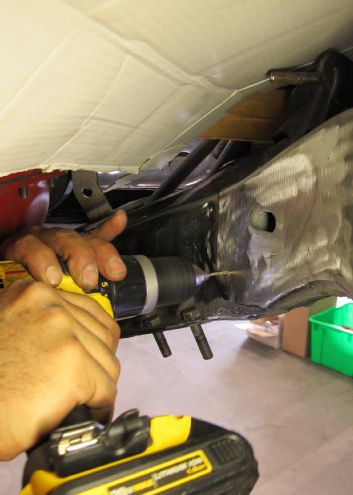
10-11. Using a pneumatic angle drill and 3/8-inch bit, the front mounting holes for the pedestals can be drilled into the crossmember once everything’s lined up and good to go.
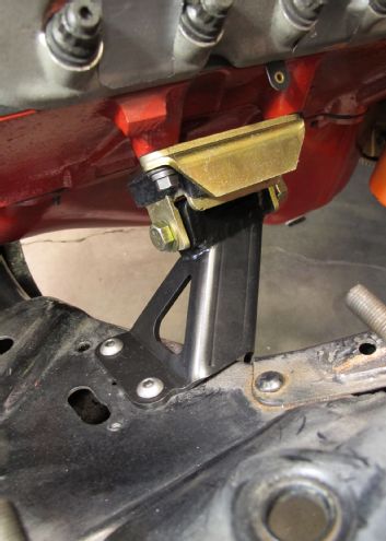
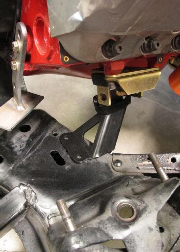
12-13. Once the pedestals are solidly mounted, the poly mounts are installed and we’re done with the engine portion.
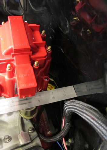
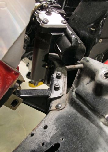
14. Proof of a successful job is in the elbow room now found between the large HEI distributor cap and the unmolested ’55 firewall—plenty to R&R the distributor … with the cap on.
15. Now to address the transmission’s minor relocation via CPP’s tubular, adjustable trans crossmember.
16. With the side bracket “ears” loosely attached, the crossmember is mounted to the transmission tailshaft and aligned onto the framerails for positioning.
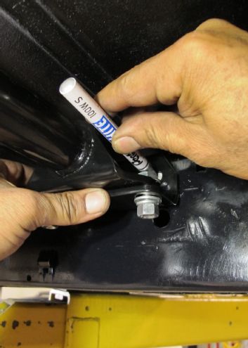
17. Once the tranny’s centered and the bar is perpendicular to the ’rails, the side bracket holes are transferred onto the frame.
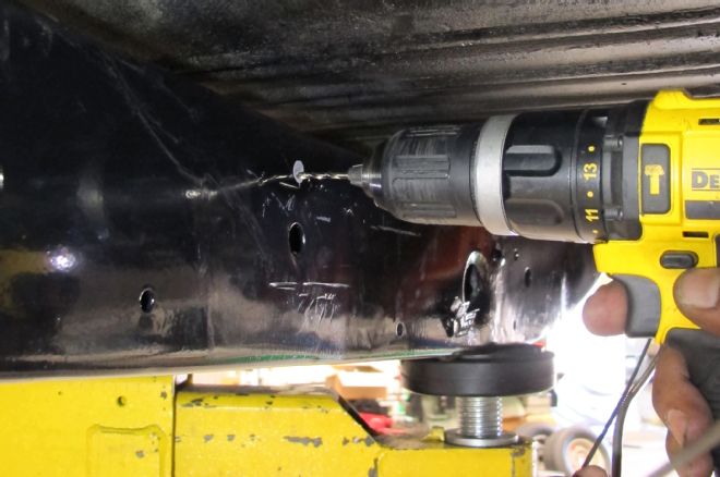
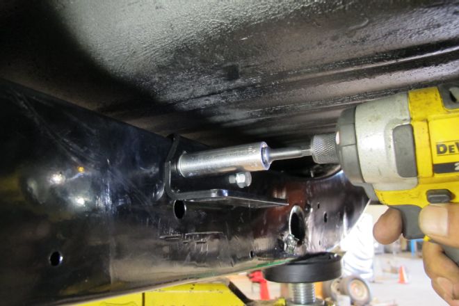
18. The framerails are then drilled accordingly using a 5/16-inch bit—the hardware supplied is 3/8-16 self-tappers, so undersizing the holes is necessary. (The transmission is supported via jack or lift during this portion.)
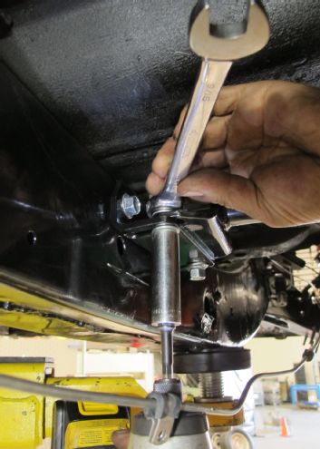
19-20. Attach the side brackets first, followed by the tube crossmember itself.
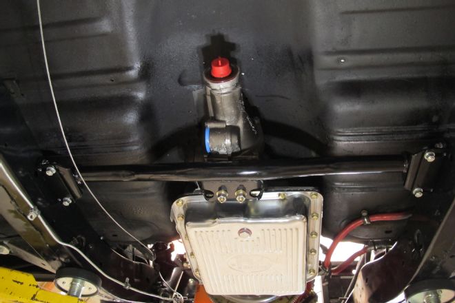
21. Using a new polyurethane mount, the 700-R4 is mated with its new adjustable crossmember and our ’55 is about ready to hit the road again.