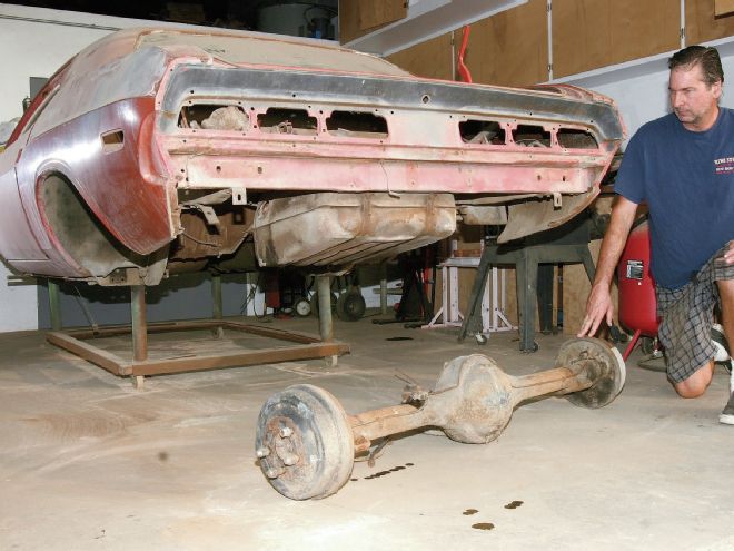
Last month we dug deep into the 8.75-inch rear end assembly from our 1971 Dodge Challenger R/T project. Like the vast majority of Mopar muscle cars, our 383 automatic Challenger came equipped with the 8.75-inch rear, and like many it was long overdue for a full overhaul. Although I have owned this car since the late 1980s, it was put aside as a future project from day one, so there was little road time to indicate the possible condition of the unit. The temptation was there to just clean it up, apply a fresh coat of paint, and call it good enough. That approach may have worked 30 years ago, but these days it pays to go through everything when involved in a major project.
The Parts
After teardown, it was clear that a major rebuild was needed. We found shot bearings, age-hardened and worn seals, dry wheel bearings, and a broken thrust block in the factory cone-clutch Auburn Sure Grip differential. This was going to be a full build. Since we were in it, it was the right time to consider the gear ratio. Because this is an automatic car, and we were after a reasonably stock-appearing restoration, an aftermarket overdrive trans or add-on overdrive were too conspicuously non-original for the build style we were after. With a rebuild of the original 727 as the only real choice, we decided to change to a set of 2.76:1 gears for easier highway cruising. This ratio is not available new from the aftermarket, but fortunately it was produced in significant numbers as OEM and we had a few gearsets in the stash. Our original Sure Grip still had some life left in it, but now was the time to add a fresh unit for years of trouble free service.
For all of our parts needs we went to Randy's Worldwide Automotive, ordering a new Auburn Sure Grip, a complete rebuild kit, and a pair of axleshaft bearing kits. While we were at it, we ordered a crush sleeve eliminator kit, which replaces the crush sleeve in a #489 case with a solid spacer and shim setup similar to earlier 8.75-inch designs. The solid spacer reduces the likelihood of pinion bearing failure under hard use and abuse, and allows the rear to be disassembled without replacing the crush sleeve each time. Our replacement gearset featured the fine 29-spline pinion, rather than the coarse 10-spline of the stock gears, so we also ordered the 29-spline yoke for a 7190 joint.
Pinion Depth and Preload
Setting up the gears involves several adjustments, the first and most critical of which is the pinion height. This is adjusted by a shim under the rear pinion bearing, and once the bearing is pressed, you are risking bearing damage by removing and reinstalling it. We honed the inside diameter of our used stock bearing to a slip fit for trial assembly. Pinion height can be checked with a special set of measuring tools and fixtures, but if you build the occasional rear, it is hard to justify the expense. Without this equipment you can still successfully build the rear, it will just take longer. The final determination of a proper pinion height is always a check of the gear mesh pattern, so we started with the OEM shim thickness of .030 inch from the old gearset and moved straight to a mock assembly.
There is no need to install the pinion seal or even the spacer or crush sleeve for mock assembly, just tighten the pinion nut enough to achieve the required preload on the bearings, about 15 in-lb turning torque or where you are feeling mild resistance when turning the pinion by hand. Next, install the carrier and set the backlash (more on that later) and check the pattern. With the correct backlash, the gear mesh pattern is strictly a product of the pinion height, and the pattern will let you know whether more or less shim is required. The factory service manual gives a good illustration of gear patterns as does the instruction book with the rebuild kit from Randy's. We were lucky and found a perfect wear pattern on the first go-around, so we were satisfied and tore it all down for final assembly.
Final assembly begins with installing the pinion, and in this case we had yet to determine the spacer shim pack to achieve the required bearing preload with our crush sleeve eliminator kit. A good starting point is to measure the length of the used crush sleeve and shim the spacer to match, then install the pinion and check the turning torque. Specifications with new bearings ran between 14 and 19 in-lb rotating torque with the pinion nut torqued to 240 ft-lb. Turning torque is most easily checked with a beam type in-lb torque wrench. If the turning torque is too high, more shim is needed; conversely, not enough torque means shim needs to be taken out. It took us several trials before zeroing in on the proper preload. Don't kill the bearings by going straight to 240 ft-lb on the first hit without checking progress, as the preload can be massive if short on shim. You can feel the bearings by rotating the flange holding tool as the nut is progressively tightened. If it starts getting tight well before reaching torque, stop and add shim.
Carrier & Backlash
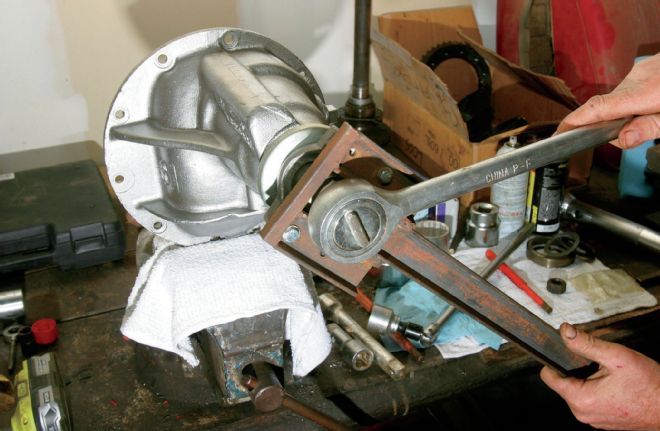
With the pinion installed, all that is left is to install the carrier and set the carrier bearing preload and backlash. The backlash is the clearance between the ring-and-pinion, and specifications are between .006 and .008 inch, measured with a dial indicator on a ring gear tooth. The preload and backlash are set at the same time and related. The ring gear carrier (differential) rides on bearings at either end, with the races floating in the housing bore. Threaded adjusters bear on the outside of the races at each side to set their position. Like the pinion bearing, the differential bearings need preload, which is set by the distance between adjusters. Tighten the adjusters towards each other and the bearings will be squeezed together against their races giving preload. To turn the adjusters you'll need a spanner wrench, which can be purchased or made from some scrap steel. While adjusting, have just one cap fastener fully torqued, while the other is just snuggly seated.
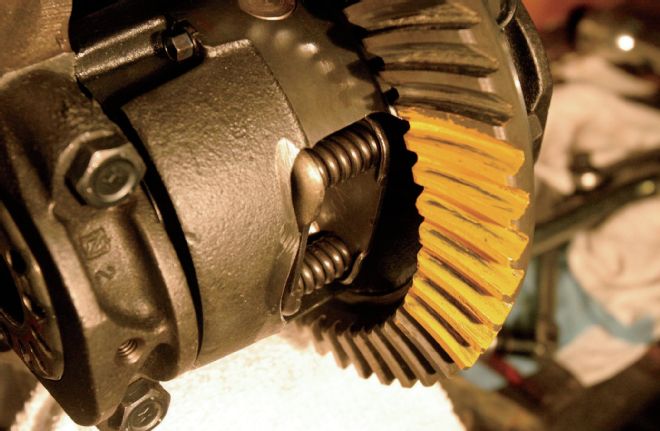
Moving the ring closer to the pinion or further away changes the backlash. The adjusters provide for the side-to-side movement. Starting at a position of excessive backlash, bring the adjusters in until the bearings are seated snug in the races, and there is no endplay. Check the backlash at various positions around the ring gear to find the position of least clearance, and make a reference mark of the position. Variation in backlash should not vary more than a maximum of about .002 inch. With the gears in the position found to have the least backlash, move both adjusters evenly until the backlash is reduced to .0005 - .0015 inch. Now tighten the pinion-side adjuster until backlash increase to the final specification of .006 - .008 inch. This sets the final preload and backlash at the same time. Once the backlash is set, torque the remaining main cap bolt. Our gearset came together with less than .001-inch variation in backlash, at .0065 - .007 inch at various points around the gear. We next rechecked the gear pattern, and it was identical to what we saw in mock-up—right on the money.
Shafted
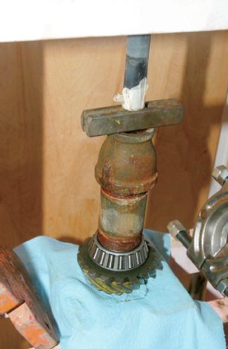
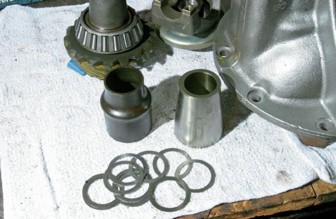
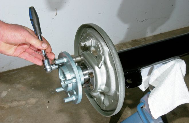
The final step in our mechanical rebuild was to replace the axleshaft bearings. The factory setup consists of the retainer/adjuster, the race and bearing, and then a lock ring. We began tearing it down by removing the lock ring. Per the factory process, the ring was staked on the circumference, which loosens the press and allows it to be driven off. We next dismantled the bearings, again using the service manual process of cutting out the bearing cage, notching the inner race flange with a grinder, and removing the bearing rollers, leaving only the inner race. This was done to provide clearance to install a bearing separator. We used a hydraulic press to finish the job and press the race from the shaft.
We found one of the shafts had some serious gouges under the bearing, no doubt from previous improper service. Flawed or gouged axleshafts are prone to failure, so we ended up replacing that shaft. We had spare stock E-Body axleshafts in our parts hoard, but Randy's can supply new axleshafts if required. The axleshaft splines are also prone to wear, and should be carefully inspected. The shafts will need to be replaced if visible spline wear is found. Our shafts looked good at the splines, so we completed the job by cleaning and pressing on a new set of green bearings from Randy's.
Finish Line
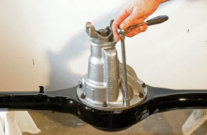
We had all of our subassemblies cleaned, painted, and rebuilt, leaving only the simple job of putting it all back together. We painted the housing with PPG gloss black urethane after blasting, and the gear housing received a custom brew of the same in a bare cast steel tint. The axle shaft flanges were similarly finished, as were the stock backing plates for the 10-inch drum brakes. The gear chunk bolts to the housing first, using the factory deep 3/8 NF nuts in bare steel. To help reduce the potential for seepage, we dressed the gasket from our rebuild kit with Permatex Aviation #2 non-hardening sealant. The factory snubber was in good shape, so it was simply refinished in gloss black and bolted in place using phosphated OE bolts. The backing plates were blasted and sprayed with urethane paint mixed to a bare stamped steel tint. We finished by installing the backing plates with the OEM-style rubber-coated steel gaskets, followed by the axleshafts using the gaskets supplied with the bearings. Our revived 8.75-inch rear was looking too nice to hide under our car, but the fully rebuilt unit is sure to provide years of reliable service.
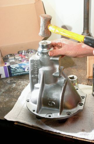
Our kit from Randy's Worldwide Automotive came with bearing, races, shims, and seals—everything needed to rebuild the gear chunk. We added a crush sleeve eliminator kit, axleshaft bearings, a new yoke to match the splines on our pinion, and a fresh Auburn Sure Grip. We began by driving the new bearing races into our cleaned and painted #489 case.
While we had the rear apart, we decided to swap the factory 3.23 gears to a more freeway-friendly 2.76 ratio. This ratio is not available new, but are plentiful from the usual used parts sources. New ring gear fasteners come with Randy's master kit. Note the ring gear bolts have a left-hand thread. We torqued to the factory spec of 55 ft-lb, and then paint marked each as a check.
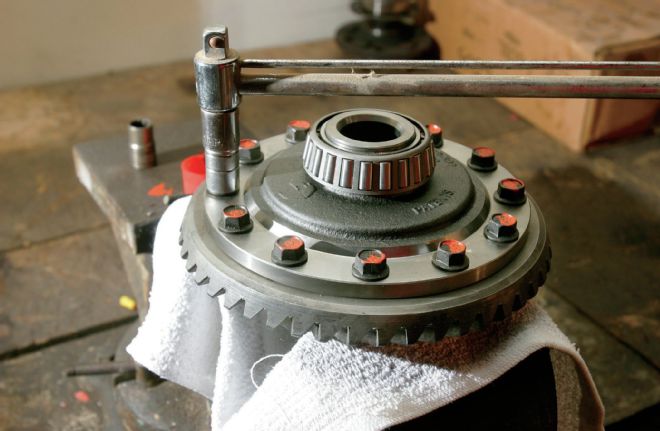
The kit's Timken bearings are a simple press-fit onto the new Auburn limited-slip differential. Always fixture to press only on the inner race, or the bearing will be damaged.
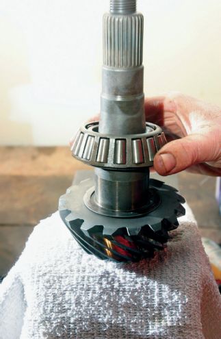
A shim behind the pinion bearing sets the critical pinion depth. Correct pinion depth is confirmed by checking the gear mesh pattern. For mock assembly, we started with the .030-inch shim from the original gearset, and honed the old bearing to a slip fit in case we needed to change the shim to make an adjustment.
There is no need for a crush sleeve, pinion bearing spacer, or oil seal during mock assembly, just tighten the pinion nut enough to provide running preload in the bearings.
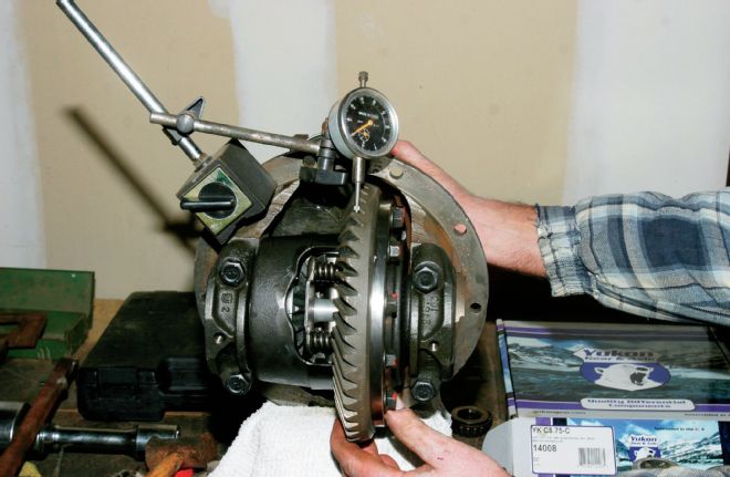
To check the gear pattern, the carrier is installed and the carrier bearing preload and backlash are set to specs. Ours was dialed in to .065-inch of backlash, and we could then check the gear mesh pattern using the gear checking compound included in our rebuild kit. The pattern will allow us to make an assessment of whether a pinion depth correction is required.
The pattern will show whether more or less pinion depth is required. Although it sometimes takes a number of trial-and-error attempts to zero-in on the required shim, our pattern looked perfect on the first hit. The carrier bearing adjuster positions were marked for reference to see if anything changes during final assembly.
Satisfied with the gear mesh pattern, we were confident in the shim setting and pulled the gear set apart for final assembly. The new pinion bearing was pressed onto our 2.76:1 ratio pinion.
Since we were eliminating the crush sleeve, we had one more aspect of the gears to set up: the shim pack required with the crush sleeve eliminator spacer. Again, this is trial and error; we started with a shim of .030 inch to match the measured length of the used crush sleeve. Several trial assemblies led us to a final shim of .037 inch, which resulted in the correct turning torque and preload.
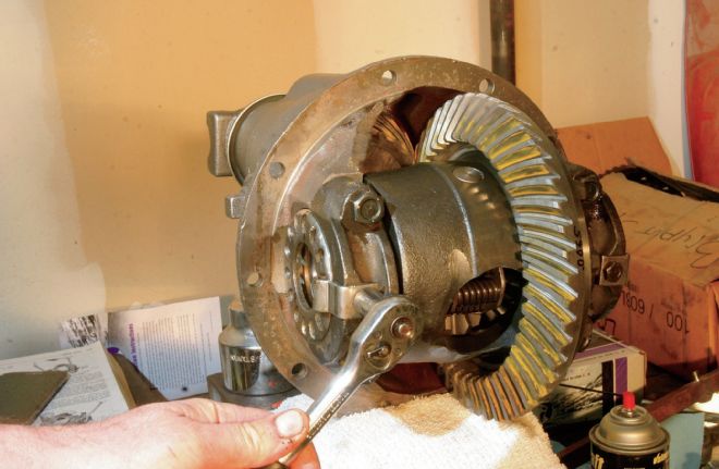
With the pinion installation completed, the differential carrier was installed and adjusted again for backlash. At the same backlash setting of .0065, the spanner adjusters landed back in the same position as in mock-up, confirmed by our reference mark. The gear mesh pattern was identical to our mock-up results. With the gear chunk completed and adjusted, we finished by torquing the cap bolts to 90 ft-lb and installing the lock tabs.
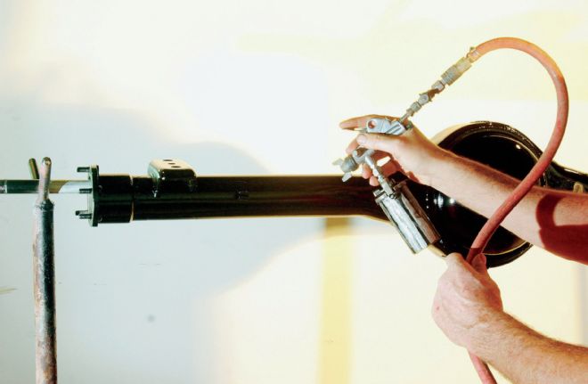
After blasting to bare metal, the housing was cleaned thoroughly and painted in PPG gloss black single-stage urethane using a Harbor Freight Tools touch-up gun.
A new gear chunk gasket was included in our rebuild kit from Randy's. We sealed it with a light bead of Permatex #2, and installed the gearset with the factory correct bare steel deep nuts, torqued to 45 ft-lb.
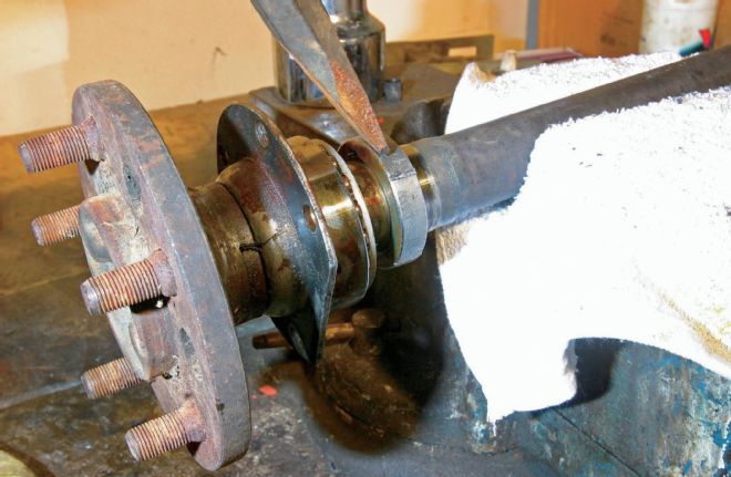
Removing the factory axleshaft bearings is not a simple press-off deal. We basically used the service manual procedure, starting with removing the lock ring. Staking the circumference with a good cold chisel releases the press allowing the ring to be walked off the shaft by chiseling as shown. Don't shortcut the job with a torch.
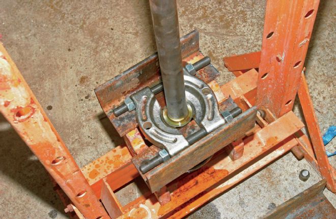
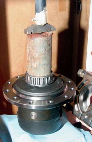
After removing the bearing cage, rollers, outer race, and adjuster, we were able to secure a standard bearing splitter to the remaining inner race. Set up in the press, the splitter needs to be well supported or the studs will bend. We used some very heavy angle iron.
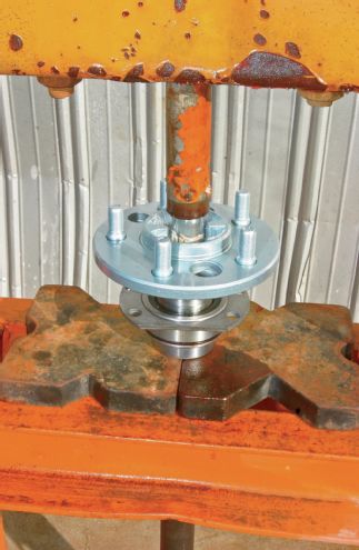
Once the axleshafts are cleaned up, installing the replacement bearings is a quick and simple press job. Be sure to slip the retainer plate in position first, and that the bearing is facing the correct direction. We pressed the bearing and retainer sleeves in two separate steps.
With new inner seals installed, the backing plates go on with a rubber-coated steel gasket to the housing ends, then the axleshafts slide into the tubes and engage the splines in the differential. Since we are using the green bearings, there is no endplay adjustment; the retainer nuts are torqued to 35 ft-lb.
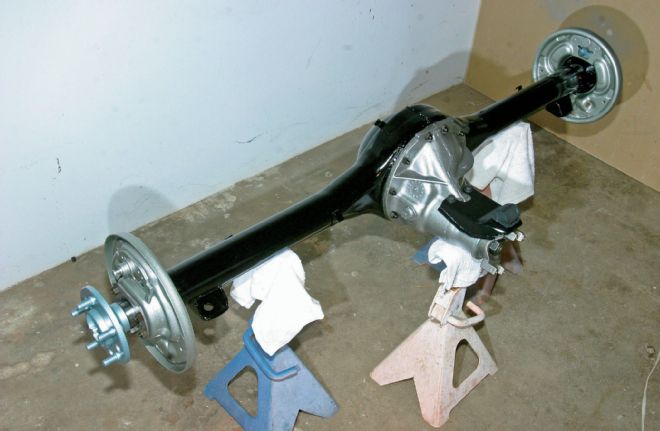
Our 8.75-inch rear looks better than new. The next job is to install it in our Chally with new suspension pieces from PST.