When it came to sourcing a rearend for our project 1956 Ford F-100, and wanting to keep the running gear "all Ford," there was really only one choice — Currie Enterprises. They've built tens of thousands of rearends over the past 50-plus years, especially since their axles became synonymous with the performance aftermarket in the '80s.
However, these days you'll find very few, if any, Ford parts inside a Currie rearend, be it an 8-, 8.8- or 9-inch version. With the availability of original parts drying up (face it, you don't see many 8- or 9-inch rears in junkyards these days) Currie undertook to produce its own axle center housings, gear cases, yokes, and differential carriers. 9-Plus products are brand-new manufactured components and assemblies, meeting or exceeding OEM specifications. The housings and covers are made from high-tensile steel, almost 40-percent stronger than conventional 1010 low-carbon steel.
Building an axle housing to a customer's required width (which previously would have been referred to as narrowing an axle casing, before new parts were used throughout) is the "easy" part, as assembling the differential is somewhat more time-consuming and technical, yet the team at Currie makes it look simple. Incidentally, all the 9-Plus components are available individually, should you want to build your own axle. Currie even sells an assembly alignment bar under its 9-Plus brand (www.new9inch.com), as well as everything from gear cases and mini-spools to T bolts, bearings, gaskets, and retainer plates.
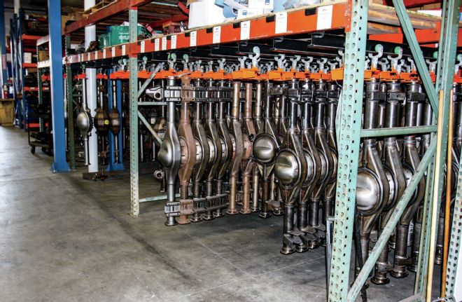
01 Currie Enterprises recently moved to a new location, allowing the opportunity to redesign its facility. The result is a near production line of rearends. Here is a portion of the stock for various applications.
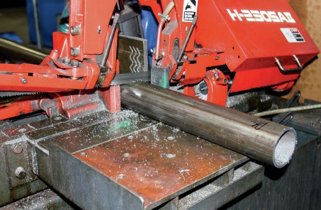
02 Once Currie has the desired width of a rearend, the axle tubes are cut to length from 3-inch diameter, 0.188-inch wall steel tubing.
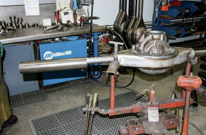
03 With the axle housing placed in a jig, a gear case is installed with collars in place of the bearings, and an alignment bar installed through the collars. The axle tubes are then put in place.
04 The bearing housings (in our case large bearing Torino-style housings), also with collars in place of the bearings, clamped in place using Vise Grips, are slid over the alignment bar, and the housing width checked.
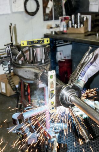
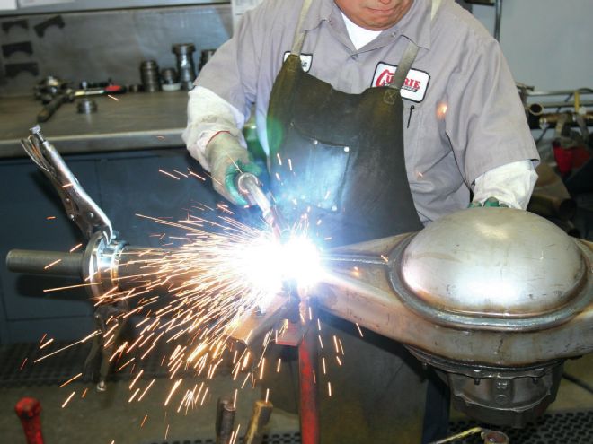
05 With the front face of the gear case set level, the bearing housings set perpendicular to that and all four bearings aligned using the bar, the assembly is tack welded.
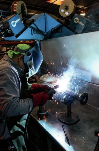
06 The entire assembly is then transferred to a slowly rotating jig for final welding.
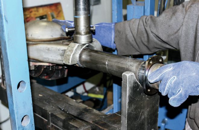
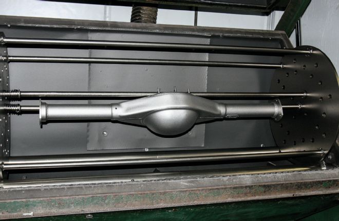
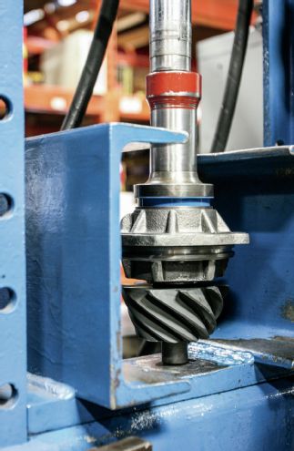
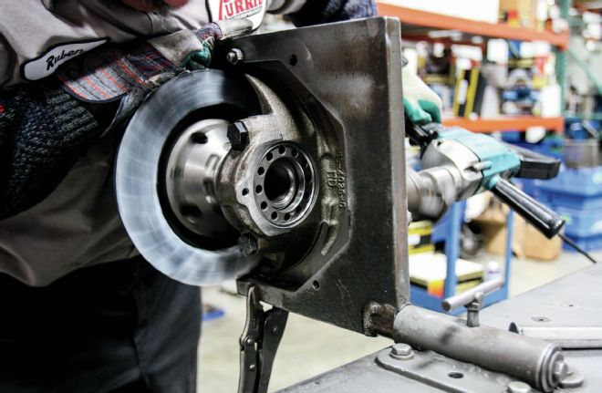
07 Once welded and cooled, the housing is moved to this heavy-duty press, which, with the assistance of another alignment bar, is used to perfectly align the bearings.
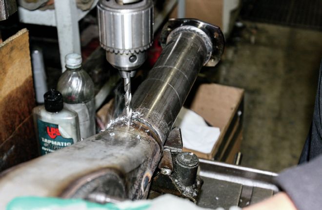
08 The housing is next drilled and tapped for a vent.
09 The completed housing is media blasted and hot tanked prior to delivery to the assembly area.
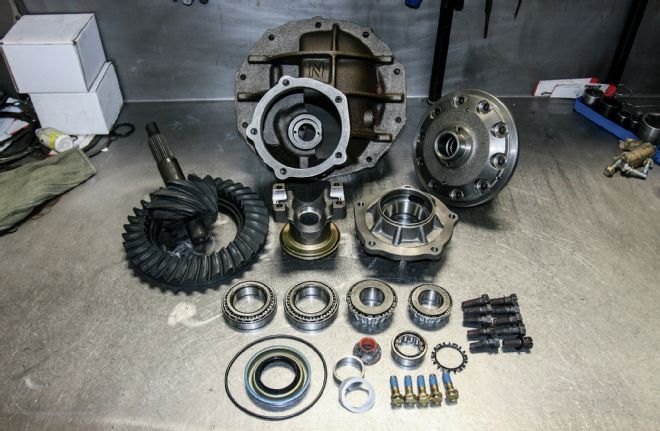
10 The new components for the third member; a 3.55:1 ring and pinion, open carrier, new yoke, and pinion support, plus bearings and bolts.
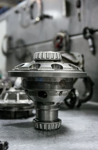
11 Assembly starts by pressing tapered bearings onto the carrier.
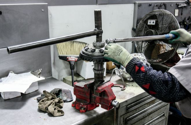
12 The ring gear is bolted to the carrier and torqued to 65 lb-ft. Note the splined tool used to hold the carrier in place while the ring gear is torqued.
13 The bearing and seal are pressed into the pinion support...
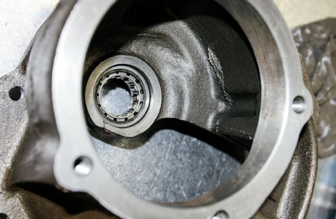
14 ...and the pocket bearing is installed in the gear case.
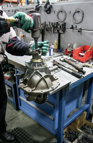
15 This jig is used to hold the gear case while it's assembled, and is capable of being flipped to work on both sides. Here the pinion support is bolted in...
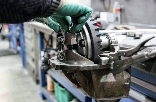
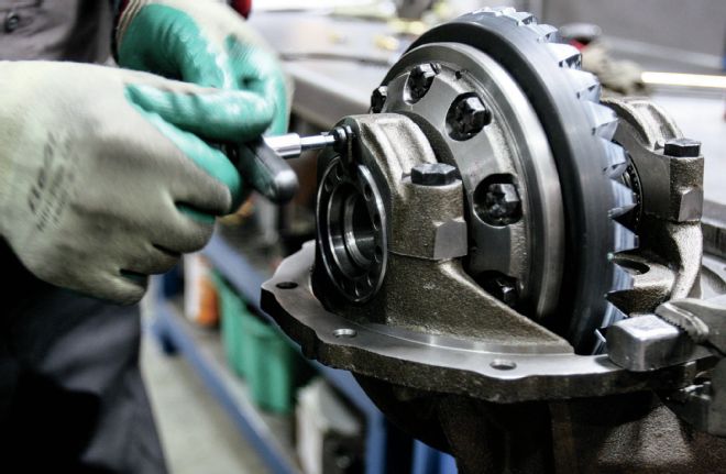
16 ... before the case is flipped and the ring gear and carrier are lowered into position. The spanner nuts and caps are then installed, the cap bolts tightened to 85 lb-ft.
17 After backlash is set using a dial gauge, depending on the gear manufacturer's recommendations, gear marking compound is applied to the ring gear to establish the contact pattern between the ring and pinion. An electric drill is used to spin the pinion to determine this.
18 Once any adjustments are made, by readjusting the spanner nuts, and the pattern is central on the ring gear teeth, these lock tabs prevent the nuts from moving.
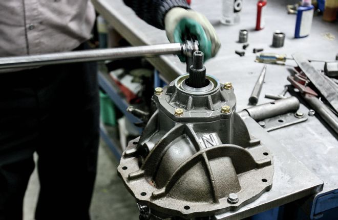
19 The yoke can now be installed on the pinion to complete the third member assembly.
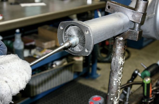
20 Moving to the assembly area, and with the rearend housing clamped in a jig, an air-powered rotary wire brush is used to clean the axle tubes of any debris.
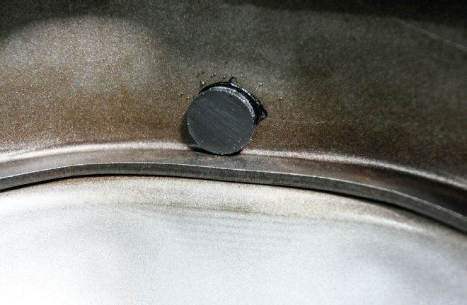
21 A magnet is glued in the bottom of the "pumpkin" to catch any metallic debris once the rearend is in use.
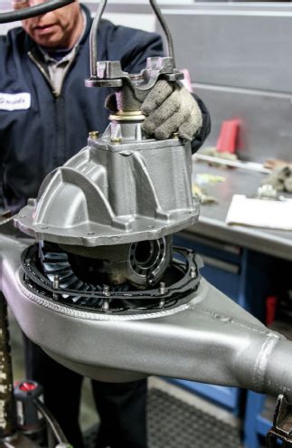
22 With a bead of RTV on both sides of the gasket, the third member is lowered into position in the casing.
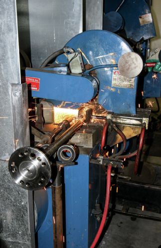
23 While the third member was being assembled, the axles were cut to length and splined.
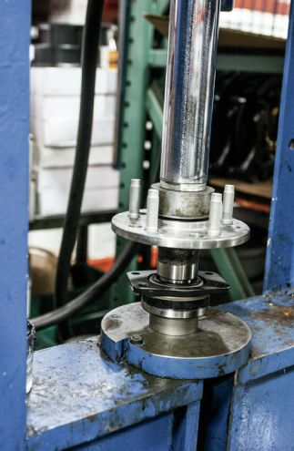
24 Currie has this neat press for installing wheel studs.
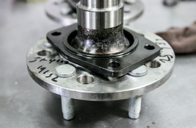
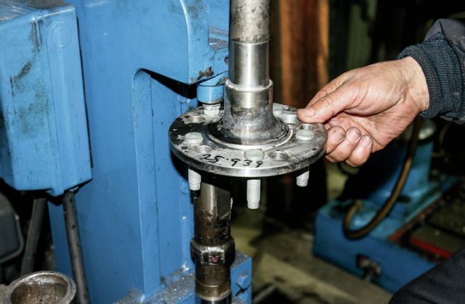
25 Do not forget to install the retainer plate prior to pressing the bearing onto the shaft!
26 With the retainer in place, the collet and bearing is pressed on.
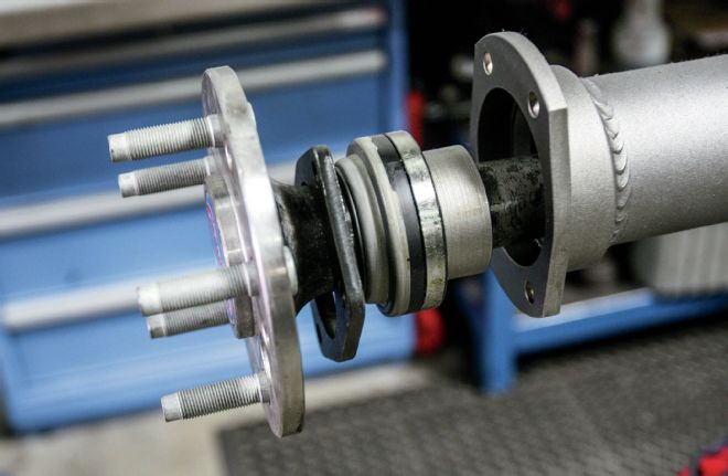
27 With a little grease on the bearings, the shafts can be installed. The retainer plates use the same studs that hold the drum brake backing plates in place, but our rearend will be using Wilwood discs. Currie can supply rearends with Wilwood discs, or with 11-inch drum brakes, using Ford-sourced internals and drums of their own manufacture.
28 Our retainer plates weren't tightened all the way down, as we'll be installing the Wilwood caliper brackets using the same studs. This is how Currie ships its rearends.
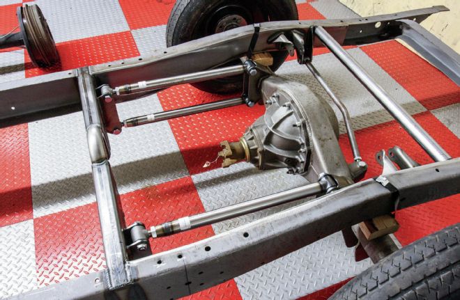
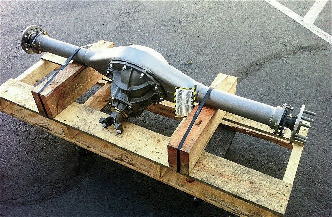
29 We shipped the rearend with the chassis to Art Morrison Enterprises, who added four-bar, coilover, and Panhard rod brackets before straightening the casing once again.
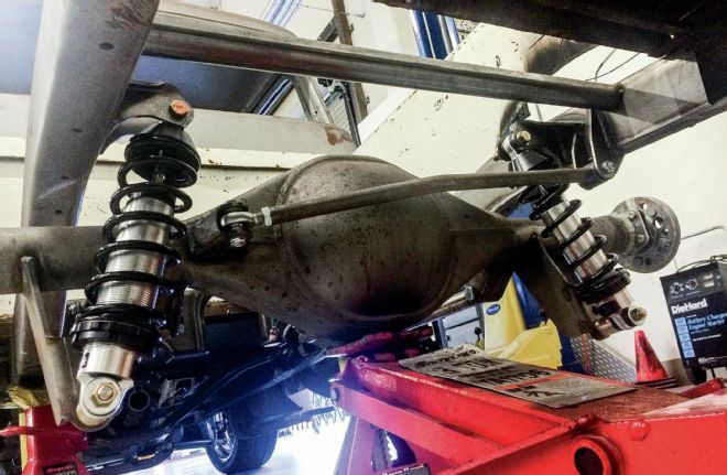
30 Hung on coilovers and showing the Panhard bar, the rearend is currently back out of the chassis as we're C-notching the rails.