When designing or choosing suspension concepts to use in your hot rod, selections are usually determined by the style of car being built. For a truly contemporary car, there's nothing like a polished independent front or rear with big-inch disc brakes, but should you choose to follow the traditional route, there are an equal amount of formulas that would look right at home. In following the traditional theme, nothing looks better under a classic hot rod more than a quick-change rear suspended by an original spring complemented by vintage radius rods.
The last time we left off at the Rolling Bones Hot Rod Shop in Greenfield Center, New York, the team had just wrapped up on one of their very signature perimeter chassis for the Deuce five-window they are building. Anyone familiar with the Rolling Bones knows that their build style is as traditional as they come, and when it was time to handle the suspension build-ups for this series, it was time to let the proverbial "cat out of the bag" and disclose a few of their trademark secrets on how they get their cars to sit so damn bitchin'.
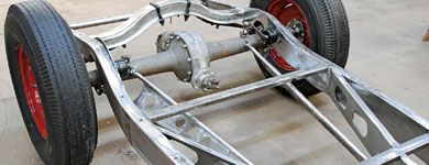
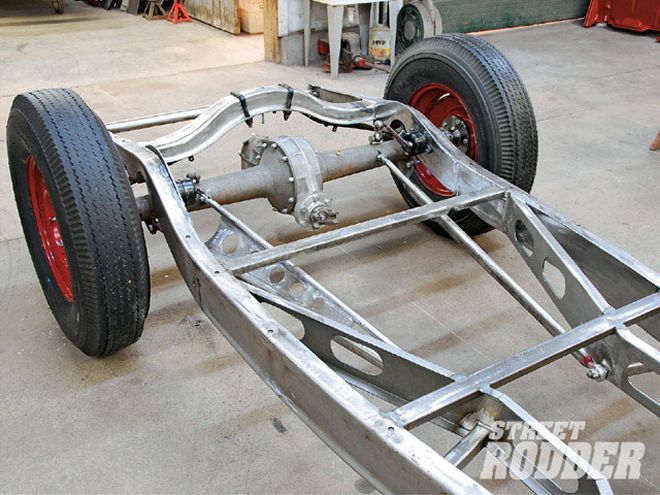
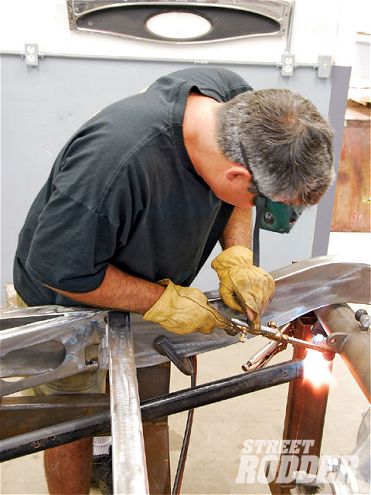
In this article we'll concentrate on the rear suspension for the Deuce. Getting things started with the freshly completed perimeter chassis still in the frame jig, Keith Cornell of Rolling Bones suspended the Halibrand V-8 quick change rearend rebuilt by the Hot Rod Works along with an original Model T spring into place. With the rearend also supported by a jack under its center section, Keith ran a string line to the center of the front crossmember from the pinion yolk while also using an angle finder attached to the front of the pinion yolk locating 0-degrees with the pinion perfectly parallel to the ground. Note that prior to the rearend being sent out to Hot Rod Works, Keith welded on his custom fabricated mounting plates which would support the new ladder bars and Houdaille shocks. At this point Keith used 1/2-inch bolts to secure the '39 Ford rear radius rod into place. Noting that the radius rod needed to be moved approximately 5 1/2-inches inboard for this application, Keith sparked up his oxy-acetylene torch to heat up the forged end of the rod in order to bend it. Once cherry red, he was able to move it into position for its new mounting point to the center crossmember. It was determined that the mounting point would need to be 3-inches back from the rear break line of the center crossmember which would require Keith to remove 14-inches from the front of the radius rod's welded seam rearward. A quick trip to the chop saw had the rod at the right length. With the rod end opening then slightly reshaped from oval to round using a disc grinder to accommodate the 3/4-inch mounting bung, Keith TIG welded it into place and then installed the new Heim joint (both parts from Speedway Motors). Some finish grinding had the rod end with the new Heim joint installed looking like it came that way from the factory.
 Start with 1/2-inch bolts to secure a stock '39 Ford radius rod to custom mounting plates modified for his application on the quick-change rearend from Hot Rod Works. Notice just how far away from the crossmember the radius rod is.
Keith then reinstalled the radius rod into place and located the exact point where he would need to secure it through the center crossmember to the boxed inner framerail. Once marked, he used a disc grinder to remove the crossmember section and then measured the amount of 1/2-inch square steel stock he would need to use for the Heim joint support mount. To create the support mount insert, Keith fabricated a 1/2-inch thick steel slug and drilled it for a 5/8-inch Grade 8 bolt to be welded into place from the inside. From there he drilled two 1/4-inch holes into opposite sides of the 1/2-inch square stock to allow him to plug weld the insert into place, followed by finish welding to give it plenty of brute strength. Keith then clamped in the support mount, checked it for levelness to the chassis, and TIG-welded it into place. With the radius rod now securely mounted, Keith bolted in a section of 7/8-inch mild steel tube (which had one end threaded to accept a 5/8-inch clevis) to the upper ladder bar mount atop the rear end. After the proper length was determined to meet the top of the radius rod, Keith trimmed it and complimented it with an angle cut across its base to allow it to meld with the radius rod and create the initial form of their signature ladder bar. Once this was tack-TIG-welded into place, Keith then tacked in the drilled center gusset for the ladder bar fashioned from 1/8-inch flat steel stock. To brace the ladder bar before being removed for final welding, Keith also tack welded some additional support straps which would later be discarded. Once the final welding was finalized and ground smooth, the ladder bar that emerged was just plain wicked.
One of the most critical moments in setting up the rear suspension involves bolting the body to the new chassis so as to set the rear wheel placement in relation to the rear wheel arch on the body. With the complete rearend and body installed Keith made the needed adjustments through the ladder bar Heim joints as well as at the rear spring perch where he picked up an additional 1/4-inch of play through the use of a '37-41 Ford spring perch to mount the Model T rear spring into place. Once it was all dialed in, Keith marked his settings, removed the body and rear wheels, and then used a level to set the exact area on the bottom of the rear framerail that would need to be opened up for the C-notch to allow ample rearend travel. That done, the rearend was again removed and the chassis was flipped upside-down in the jig for Keith to perform the surgery for the C-notch. Since the C-notched area receives a demanding amount of stress from the rear suspension, it's imperative to pay close attention during the reworking of the chassis rail. Keith used a plasma cutter to open the rail up and then followed by cutting a section of 1/4-inch steel tube in the chop saw to prepare for its installation. With everything deburred and ready to go, Keith TIG welded the new section into place followed by a final grinding to add a nice clean look. A modified rubber snubber from Early Ford V-8 Sales, Inc was then added to complete the area. It was at this time that he also notched the area adjacent to the C-notch to accommodate travel of the Model T rear spring as well.
Coming around third base and heading for home, Keith flipped the chassis back over in the jig one last time, reinstalled the rearend, checked everything for levelness, and readied for the installation of the inboard mounted Houdaille shocks. To add in additional strength to the C-notched area for the shock application, Keith fashioned an additional bracing plate from 3/16-inch flat steel stock and then clamped it into place on the inside rail of the chassis. With a modified '37-41 Ford shock ball mount welded to the top of the rear axle housing being used as a guide, Keith then clamped a Houdaille shock to the inside of the framerail to determine its proper placement. It was then time to bolt on a '40s-era Ford shock arm and determine the amount of adjustment that it would need to line up with the shock ball mount atop the rearend. Using an oxy-acetylene torch, Keith heated up the arm and they moved it into its final position to be able to mount the 1-inch shortened Ford dog bone into place. In a final step before the final TIG welding could be completed, Keith used a 3/8-inch drill bit to allow a pair of 3/8-inch nuts to be welded to the backside of the bracing plate to mount the shock and a 1-inch hole saw to drill through the inner framerail boxing plate to accommodate the mounting nuts. Once completed, Keith chased the shock mounting holes with a tap to rid them of any welding debris before assembling the completed suspension.
Well, there you have it-half of the suspension secrets from the inner sanctum of the Rolling Bones Hot Rod Shop have been revealed, but stay tuned, cuz directly following, we'll let you in on how they trick the Devil into letting them get their front ends so darn low using an un-dropped factory Ford axle.