The Combo
Bob Momcilovich’s Lake of the Woods, California–based ’64½ Mustang currently runs a ’68 289ci V8 backed by a wide-ratio Ford Top Loader four-speed trans and 8-inch Ford rearend stuffed with a Traction-Lok diff and 3.23:1 gears. The motor is warmed-over with a healthy Comp Cams flat-tappet hydraulic cam, an Edelbrock single-plane Torker intake fed by a 650-cfm Holley Ultra Double-Pumper carb, a PerTronix breakerless conversion kit in the original Ford points distributor that’s boosted by a MSD-6A ignition box, and long-tube headers. Bob also installed a ’68–’73 Mustang front disc brake setup and dual master cylinder.
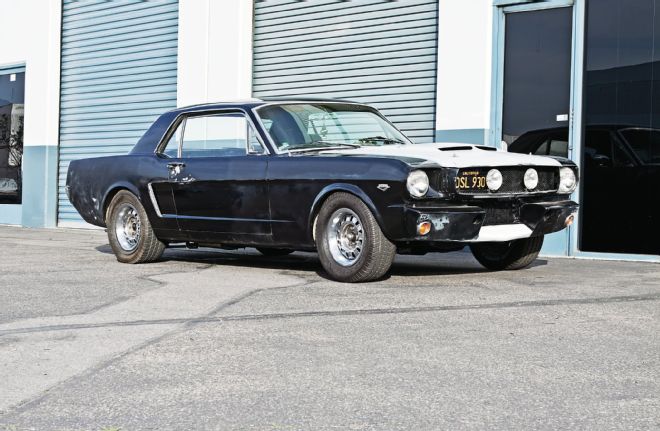 Originally built with the 271hp, 289ci, high-performance engine and T10 four-speed, it now runs a later 289 and Ford Top Loader trans.
Like most Fords of its era, the car used a lever-style Long clutch. For street use, Long clutches—especially when upgraded from OE configuration—can be overly stiff with harsh engagement characteristics. A few years ago, Bob’s clutch gave up the ghost. He replaced it with a stiffer aftermarket Long clutch and 164-tooth steel flywheel, all ensconced in a scattershield.
The Problem
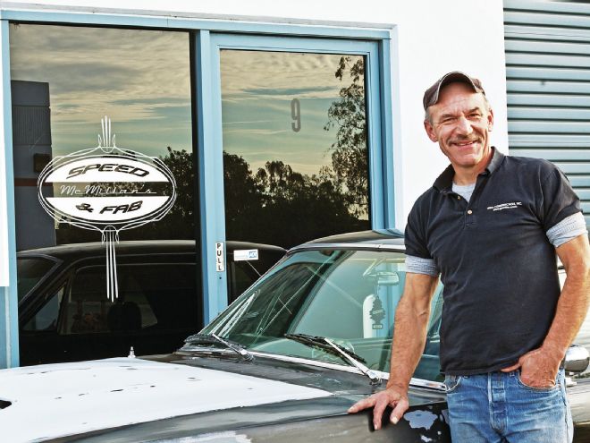
At this point, Bob says “the clutch pedal became virtually impossible to push down. It was as hard as a rock. Looking at the installation, for some reason the fork seemed too close to the pressure plate. It didn’t seem to have the right pivot arc. The clutch also vibrated a lot and didn’t engage smoothly.” Eventually, high pedal pressures plus apparently incorrect linkage geometry broke the mechanical clutch linkage’s Z-bar pivot-stud boss completely off the block. Bob tried to fab an adapter bracket to take its place, “but it didn’t work very well.” That’s where we entered the picture, sending the car to Kevin McMillan’s McMillan Speed and Fabrication, a well-known car builder and fabricator located in Oxnard, California.
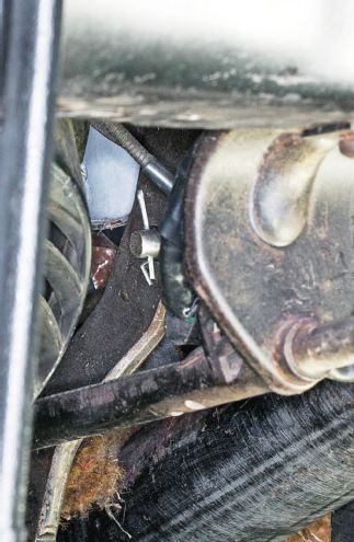
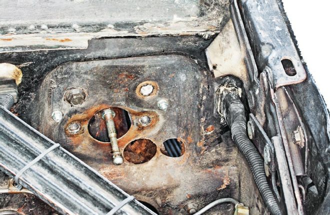
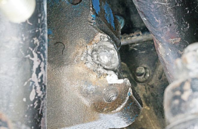 Missing linkage: The Z-bar pivot-stud boss cracked off the block, likely due to the pressure plate overstressing the old clutch linkage.
The Diagnosis
 Clutch rescue: Car builder and fabricator Kevin McMillan, head honcho at McMillan’s Speed and Fabrication, performed the repair.
The broken car wasn’t driveable when it arrived at the shop, so it’s impossible to determine for sure the problem’s exact cause. But generally, any combination of the following could cause a massive failure like this:
The Possible Solutions
Short of getting a new block, there’s no practical way to repair the broken Z-bar pivot ball. Alternative solutions include:
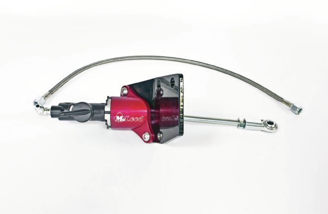 Evolution: McLeod’s model-specific hydraulic clutch conversion kit bypassed the broken block while vastly improving clutch feel.
Install an aftermarket mechanical linkage bracket: Late-model Ford factory small-blocks (including Ford crate motors) no longer have pivot-ball boss provisions cast into the block. Bolt-on pivot-ball brackets were developed for retrofitting the later engines into early cars. Although it would provide an immediate solution for the broken Z-bar pivot, it wouldn’t resolve the owner’s stiff linkage complaint.
Install a cable-actuated clutch: Besides the cable and underdash clutch quadrant, this conversion requires a late-model diaphragm clutch and a cable-clutch–compatible bellhousing and fork. The deal-breaker was the difficulty of smoothly snaking the cable around and through the old Mustang’s full-length headers.
Install a hydraulically actuated clutch: A properly engineered conversion kit replicates the easy, smooth pedal and shift effort of today’s cars and trucks, virtually all of which use hydraulic linkage.
Although it’s possible to hydraulically actuate a Long clutch, today’s passenger-car conversion kits work best with a diaphragm pressure plate. After consulting with Bob, Kevin McMillan selected a hydraulically actuated diaphragm clutch as the best fit for his Mustang. McLeod Racing offers a “one-stop” integrated solution with its clutch, hydraulic master-cylinder conversion kit, and modern-car–style integral hydraulic release bearing.
The Fix: Flywheel and Clutch
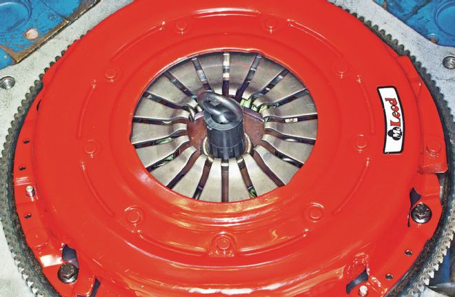
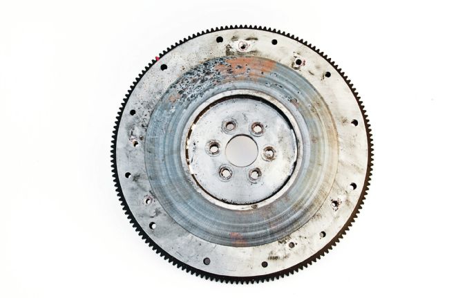 Bob’s old Long-style flywheel, three-finger pressure plate, pilot bushing, and mechanical throwout bearing showed signs of improper installation, damage, and overall distress. The beefy 2,500-pound pressure plate lacks the antirotation locating dowels like those found on today’s race-style Long clutches. It may have developed too much pressure for the stock Ford mechanical clutch linkage. Note the broken clip (arrow) on the throwout bearing.
Bob’s existing clutch and flywheel setup used a late-’60s-style, Ford 164-tooth flywheel and Long-style clutch. The massive aftermarket scattershield barely cleared the exhaust headers. In theory it supports both 164- and 157-tooth flywheels—but to be able to do this, it’s much bulkier than the stock 157-tooth bellhousings typically used on tight, early first-gen Mustangs. Fortunately, Bob still had the original factory 157-tooth–compatible aluminum bellhousing. In our experience, the factory units are usually dead on in terms of runout (assuming the block itself is accurate), they save space in an old Mustang, and the most popular hydraulic clutch conversion kits perform best with the smaller, lighter, 157-tooth flywheels. For these reasons, McMillan reverted to the original aluminum bellhousing, packing it with a new 157-tooth McLeod steel flywheel, plus its Street Pro diaphragm pressure plate and clutch kit. Capable of supporting around 360 hp, the basic configuration is very popular for late-’80s Mustangs whether they’re still running original cable clutch linkage or have been converted to hydraulic linkage. Be sure the clutch disc is for the stock Top Loader’s 10-spline, 11⁄16-inch-od input shaft.
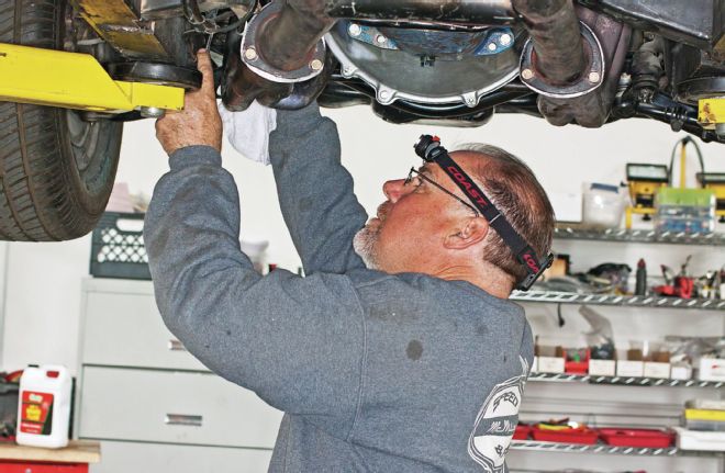
Installing the clutch requires removing the rear exhaust pipes, transmission, transmission shift linkage, and driveshaft. During this process, McMillan found and fixed one marginal driveshaft U-joint. The rear dual pipes were badly welded, so they were cleaned up and repaired as well. When reassembling, it may be necessary to readjust the shift linkage. Check out a factory service manual if you’re not sure on the proper rod sequencing and adjustment procedure.
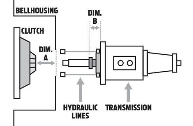
Pedal Ratio Explained
The push force exerted by your leg on the clutch pedal requires a multiplier to transmit sufficient force for actuating mechanical clutch linkage or developing a hydraulic cylinder piston’s full stroke. On a hydraulic clutch, the full multiplier is developed by the “pedal ratio” (C). There are two key dimensions needed for establishing this ratio:
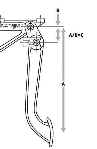
Pedal length: The pedal’s center-to-center length from the foot pad to the top pivot point where it attaches to the pedal mount (A).
Pedal pivot-to-pushrod distance: The center-to-center length from the pivot point to either the point where the master-cylinder pushrod attaches to the pedal (B) or (if not connected directly to the pedal) the point at which the rod attaches to any adapter bracket that connects to the pedal.
Dividing A by B derives the pedal ratio (A ÷ B = C). For example, if A is 9 inches and B is 1.5 inches, then pedal ratio (C) is 6:1 (9 ÷ 1.5 = 6). “6:1” means that if you apply 100 pounds of pressure to the clutch pedal, 600 pounds of force is exerted on the master-cylinder pushrod (100 × 6 = 600). McLeod’s kits come with a Wilwood ¾-inch-od clutch master cylinder and operate best with a 6:1 ratio.
The Fix: Starter
 Driveline Components’ ministarter mates to the new 157-tooth flywheel. Its universal design can accommodate the larger 164-tooth flywheel by adding a spacer ring. At just 12 pounds, it’s about 9 pounds lighter than a stocker (rear). For tight clearance scenarios, the drive-end can be unbolted from the main body, then rotated to any one of three different positions.
Ford starters bolt to the bellhousing, not the block. OE-type starters need to match the flywheel in use (157- or 164-tooth). Driveline Components supplied a powerful, universal-fit, gear-reduction ministarter that mates up with either-size flywheel and develops 1.4 kW of cranking power (compared to 0.7 kW for a typical starter). That’s enough to crank anything this side of a magneto-controlled Hemi fueler. The block plate with its corresponding starter pilot-hole is a standard replacement part.
The Fix: Hydraulic Linkage Kit
The heart of the rescue is one of McLeod’s Direct-Fit hydraulic linkage conversion kits. McLeod avoids universal parts in favor of complete kits engineered for specific models, in this case a ’641⁄2–’66 Ford Mustang. In the Mustang’s case, the McLeod kit requires drilling a new pushrod hole in the firewall, plus there’s a discrete adapter included in the kit for connecting the pushrod to the pedal.
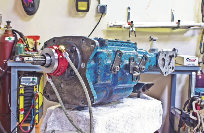
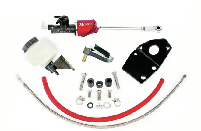 The hydraulic conversion kit includes all necessary parts except a hydraulic throwout bearing. The proper bearing will vary according to the combo’s bellhousing, clutch design, and trans.
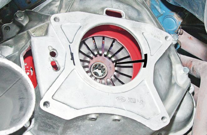
 Although an old trans input shaft works best for aligning the pressure plate and clutch disc splines with the pilot bushing, McLeod supplies a useful plastic alignment tool in its kits. Use metric bolts to attach the plate to the flywheel, then bolt-on the bellhousing.
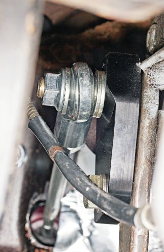
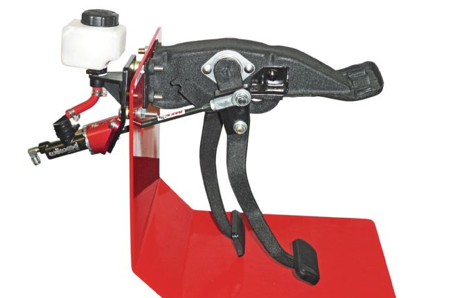 McLeod’s hydraulic clutch linkage conversion kits are different than most of its competitors because they’re designed for a straight push on the master-cylinder pushrod (no lost motion), as well as engineered to develop the correct pedal ratio for the ¾-inch-od–bore clutch master cylinder used in the kits. Key in establishing the proper ratio and rod angle is an adapter bracket (arrow) that connects the pushrod to the pedal.
 Remove the mechanical clutch linkage and any return springs. Disconnect the old pushrod from the pedal by pulling off the stock retaining clip. Old Ford Mustangs are very tight near the brake master cylinder, and even tighter under the dash. McMillan says the hardest part of the job was physically hooking up everything under the dash: “Everything’s extremely tight.”
Why not just use the mechanical linkage firewall pass-through location and attach the pushrod directly to the existing pedal hookup point without an adapter? McLeod’s Fred Taylor says it would yield insufficient pedal ratio, resulting in a stiff and poorly modulated pedal—which obviously nullifies the advantage of converting to hydraulics in the first place. With mechanical linkage, there’s an additional ratio multiplier effect through the rest of the linkage at the Z-bar and clutch fork that’s not applicable to a hydraulic configuration. At the pedal, without the downstream multipliers, the existing mechanical linkage pedal develops about a 3:1 ratio, but you want about 6:1 with the straight-push hydraulic pushrod—hence the adapter bracket that corrects these issues.
 Here are the completed firewall mods, showing the new bolt-mounting hole and pushrod pass-through hole. Bolt on the plate for good. An underdash helper is needed to hold the nut while tightening the bracket’s right-hand bolt.
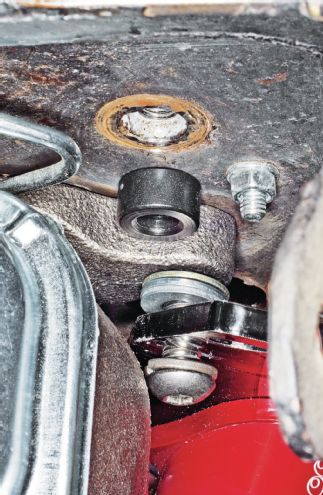 For manual-brake cars like Bob’s, the instructions say to use one long and one short spacer on the two left-hand, mounting-plate boltholes. The short 0.800-inch spacer fits between the plate and brake cylinder’s right-side bolt boss. Perhaps due to the later dual master, it was too long; instead, McMillan stacked 7⁄32-inch worth of common 3⁄8 washers to gain the right spacing.
 Install the new clutch master cylinder to the mounting plate, passing its pushrod through the firewall. Install the pedal adapter bracket to the clutch pedal, with its stud on top. Place the pushrod’s rod end over the stud and tighten its retaining nut. If necessary, adjust the pedal height by loosening the jam nut and rotating the rod.
 The fluid reservoir must mount higher than the clutch master cylinder. McMillan bolted the reservoir to the rear of the driver-side shock tower with No. 12 self-tapping sheetmetal screws. McLeod has since added threaded reservoir mounting plate holes to the clutch master-cylinder mounting plate.
The Fix: Integral Release Bearing
Nearly as tough as getting everything together underdash is selecting the proper release (throwout) bearing. Unlike a mechanical clutch that needs free play before the pedal contacts the pressure plate’s fingers or levers and therefore requires periodic free-play adjustments to compensate for clutch-disc wear, under running conditions, a self-adjusting integral hydraulic release bearing should always be in light, constant contact with the fingers—which means it also has to have enough travel to compensate for clutch wear.
To order the proper-length release bearing, you first need to know the installed distance between the pressure-plate fingers’ high point and the bellhousing rear (trans-mounting) surface (sidebar, Dimension A). It came out to 3.25 inches on this Mustang.
Due to the huge variety of possible engine-trans-clutch-bellhousing combos out there, it’s impossible to predict with any degree of certainty the proper release bearing for a given combo. The bearing should be ordered separately, after the rest of the system is together and the critical real-world clearances have been measured. Think of it like assembling a trick cam and valvetrain on a built engine: There’s no way to tell for sure what the proper pushrod length needs to be until the rest of the cam and valvetrain is mocked up and the valvetrain geometry established. McLeod offers several different bearing styles and lengths for the Ford small-block Top Loader transmission. The “Release Bearing Selection” sidebar lists the critical clearance dimensions and available bearings.
After reinstalling the trans and connecting the fluid lines, add DOT-3 or DOT-4 brake fluid to the clutch reservoir and bleed the system. Do not use DOT-5 (silicone-based) fluid; it’s not compatible with the bearing’s seals.
Release Bearing Selection
The release bearing needs to have the proper initial installation clearance so the bearing can compensate for future disc wear. Bolt the bellhousing, flywheel, disc, and pressure plate to the engine. Measure the distance from the rear (trans-mounting) bellhousing surface to the top of the pressure plate’s release fingers (dimension A). Use this measurement to order the proper bearing. McLeod offers three different length bearings that fit the Ford 11⁄16-inch-od x 10-spline trans input shaft and bearing retainer collar (table).
Install the selected bearing on the trans. On a slip-on bearing, the tapered side of the jackscrew or (if present) the spacer should seat against the base of the transmission bearing-retainer collar. Initially, the jackscrew should be screwed all the way into the bearing assembly. Measure the distance from the trans’ front mounting face to the front of the release bearing (B), and subtract it from A. This allows the bearing to self-adjust and compensate for future clutch wear (A – B = Clearance). The recommended clearance value is 0.100–0.150 inch. Screw the jackscrew out to reduce clearance. Removing or sanding down the nontapered end of the jackscrew and/or any spacers will gain additional clearance beyond that which a fully seated jackscrew provides.
For this installation, Dimension A was measured at 3.250 inches—right on the “bubble” between two of the available bearings: PN 1400-30 and PN 1406-30. McMillan chose the shorter PN 1400-30, because, he says, “as-installed in this installation with its supplied spacer the jackscrew would be fully retracted, resulting in a more rigid assembly.” With the 1400-30 bearing, dimension B was measured at 3.170 inches with the jackscrew fully retracted and the spacer in place, yielding an initial bearing-to-finger clearance reading of 0.080 (3.25 – 3.170 = 0.080). McMillan sanded the spacer down by 0.030 to increase clearance to 0.110, within McLeod’s recommended clearance range: (0.080 + 0.030 = 0.110). Note that this clearance is only the static value needed at initial installation. Once the system is pressurized and bled, hydraulic pressure pushes the bearing forward so it’s always in light contact with the pressure-plate fingers.
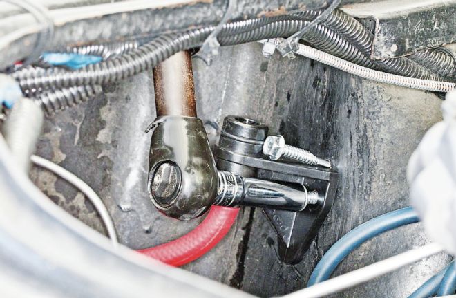
 Rotate the bearing or swap the hoses on the bearing as needed so the bleeder hose ends up higher than the supply hose. McLeod says you may need to tie a string around the hoses to help pull them through the opening in the side of the bellhousing.
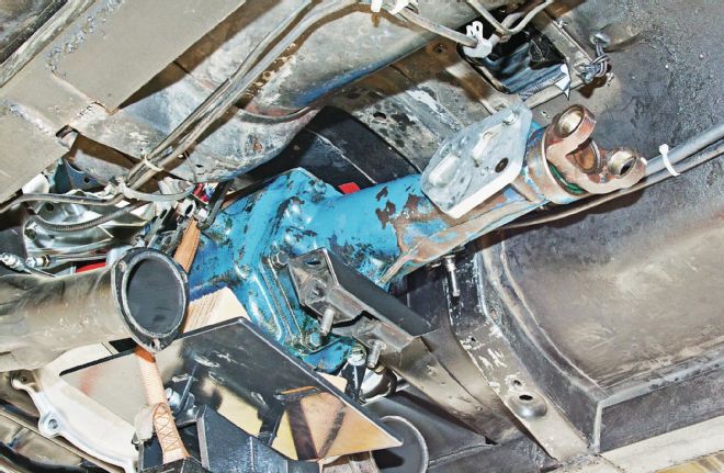 Install the bearing on the trans and the trans on the bellhousing. Install the trans shift linkage, crossmember, and driveshaft. Connect the pressure hoses between the clutch master cylinder and the release bearing.
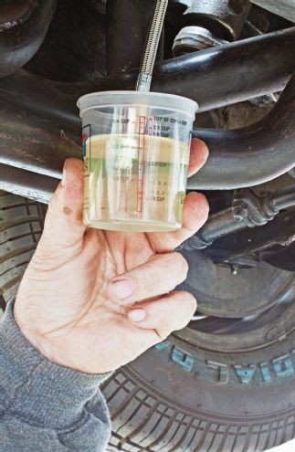 Fill the clutch reservoir. Open the valve on the bleeder-screw hose and place it in a small jar partially filled with brake fluid. Bleed the system by pumping the clutch pedal three to four times until no bubbles are visible in the jar. Refill the master-cylinder so the fluid level is ½–¾ Inch from the top; unlike brakes, the fluid level rises as the clutch wears.
Results
Bob says the new clutch “feels really nice when its released, similar to my late-model Mustang. With my old heavy-duty Long clutch, my leg would be sore the next day!” McMillan, who has performed a number of hydraulic conversions on the high-end custom cars his shop usually sees, says, “I think it runs great. The clutch works fantastic. Clutch travel and modulation of the hydraulic throwout are very linear—not always the case with some of these conversions.”
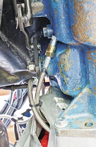 Tie off or clamp the clutch hoses to keep them from chafing and/or contacting heat sources like the exhaust headers.
Lessons Learned
Don’t “over-clutch” your street-driven car, especially with 50-year-old clutch linkage. If something doesn’t feel right, it probably isn’t right. Figure out what went wrong before a catastrophic failure occurs. On a relatively complex conversion, verify you have the right parts and tools for the job. Check the parts received against the instructions and make sure you understand those instructions.
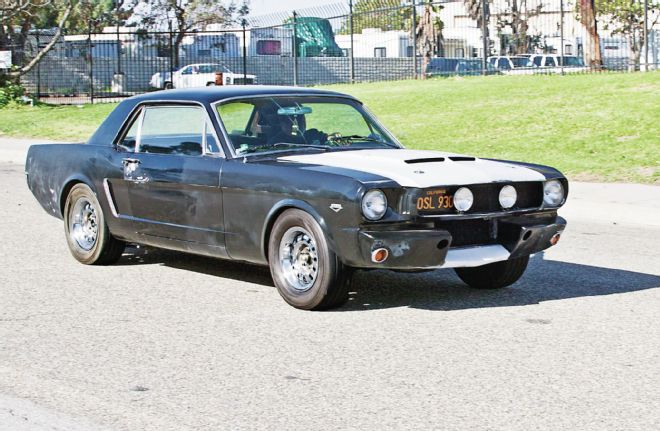 Oh, what a release it is! Clutch fixed, Bob next plans to upgrade the suspension and get the body and paint straightened out.
Need Junk Fixed?
If your car has a gremlin that just won’t quit, you could be chosen for Hot Rod to the Rescue. Email us at pitstop@HotRod.com and put “Rescue” in the subject line. Include a description of your problem, your location, and a daytime phone number.