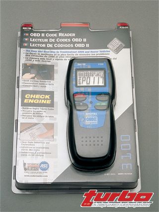
 | The hand-held Equus 3100 OBD-II code reader is versatile and easy to use. Just plug it into the diagnostic port, hit the link key, and wait for the codes to flow. The owner's manual has more than 50 pages of code definitions to ensure you can trace any troubleshooting problem back to the source.
In the Last diagnostics article, we outlined how to retrieve and decipher engine diagnostics for engines running OBD-I engine management computers. OBD or On Board Diagnostics is a subsystem of the car's ECU that can monitor the engine's emissions system.
When there's a failure in emissions components or if the engine runs in an inefficient manner (misfires, air-fuel ratio etc.) the check-engine lights up and the computer records the error code in its memory. In our last Diagnostics article, we highlighted the code reading tools and other techniques needed to get codes from domestic and imported vehicles, touched on the basics of retrieving codes and outlined the meanings of those codes.
Here, we're picking up in 1996 when the emission system computer was updated and standardized. This meant all the different methods of retrieving codes were standardized, right down to the diagnostic port plug that connects the computer to a code reader. The plug is located inside the cabin, either under the center dash, left dash or behind the ashtray.
However, it's the software side of OBD where the big changes went down in 1996. Basically, the OBD system was changed from reading whether or not the emission system was functioning to how well it was functioning. OBD-I was looking for a yes or no answer. The problem is, emission systems do not fail all at once, they tend to deteriorate over time or run at, say, 25 percent efficiency. Second-generation OBD systems are precise enough to sniff out these shortfallings. OBD-II monitors more sensors and systems, is capable of detecting more errors and even saves a snapshot of engine operating parameters at the time of an error.
 | Diagnostics 3 OBD-II Code Breaking
Monitoring
Generally speaking, there are 11 different OBD-II monitors, which can be divided into two groups; continuous and single. Continuous monitors are made up of a CCM (Comprehensive Component Monitor), Misfire Monitor and Fuel System Monitor. The single-type monitors perform their assigned task once per driving cycle. These monitors consist of Oxygen Sensor Monitor, Oxygen Sensor Heater Monitor, Catalyst Monitor, Heated Catalyst Heater Monitor, EGR Monitor, EVAP Monitor, Secondary Air System Monitor, Air Conditioning Monitor.
OBD-II Type Casting
An OBD-II trouble code comes in two varieties. Type 1 codes trigger the check engine light immediately after a failure is detected. If the check engine light is flashing, that means there's dangerous misfire that can damage the catalytic converter. The proper code is saved in the computer's memory and a snapshot of the engine's operating parameters is taken. These parameters include fuel system status, engine load, water temperature, fuel ratio, MAP vacuum and engine speed.
A Type 2 code is detected but the check engine light is not immediately illuminated. This "pending" code is saved in the ECU's memory. If the code is fired during the next drive cycle, the ECU trips the check engine light and takes an engine parameter snapshot. If there is no repeat in error, the pending code is erased.
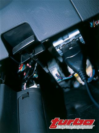 | The OBD-II connection port is standardized to make data retrieval a snap. Typically, the plug is located inside the cabin, either under the center dash, left dash or behind the ashtray.
Once the check engine light is tripped, it'll stay illuminated until the conditions that triggered the light are no longer present for three consecutive driving cycles. If this occurs, the light will go off but the code will remain in the memory for 40 cycles.
Code Grabbing
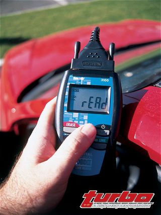
To illustrate OBD-II code grabbing, we are using an Equus 3100 code reader that can be ordered direct from J.C. Whitney. The code reader is plugged into the diagnostic port, the key is switched on and the Link button is pressed. If the check engine light is on, the unit will flash a five-digit code, which reveals where the trouble code originated. If there's more than one code in the memory, the scroll button is used to move through the codes.
 | Diagnostics 3 OBD-II Code Breaking
The code is broken down into a letter and four numbers. The letter indicates the system where the failure was detected. The first digit identifies the code as a generic or manufacturer-specific entity. The second digit indicates the sub system responsible for the code. The final two zero in on the component or component group that has failed. It should be noted that the snapshot data is only retrievable with a scan tool with a more sophisticated and expensive tool. The Equus 3100 code reader comes with a manual that has more than 50 pages of code definitions.
The code reader merely identifies the troublesome system and the course of action beyond initial identification depends on many other factors. But limiting the realm of possibilities is an important first step to curing what ails. If information is power, this unit is an excellent candidate for the savvy enthusiast's toolbox.
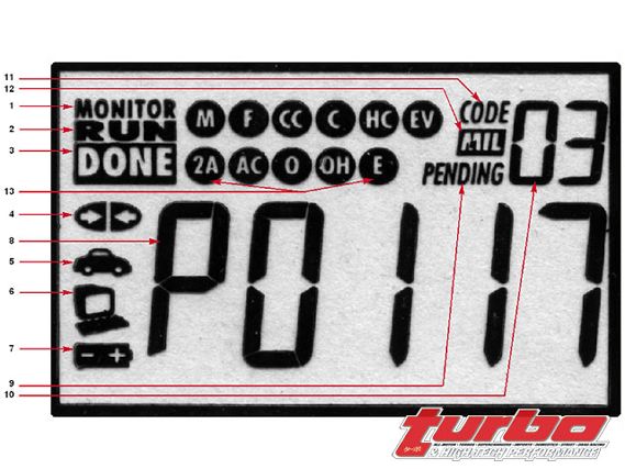
LED Screen Breakdown
1.Monitor Icon
2.Run Icon-indicates the status of the device
3.Done Icon-indicates the vehicle test is complete
4.Link Icon-indicates the reader is linked to the ECU
5.Vehicle Icon-indicates that the reader is being powered by the vehicle
6.Computer Icon-used for expanding the system via computer link
7.Reader Battery Icon-indicates the battery status of the battery inside the reader
8.DTC Display Area-where the trouble code appears on the reader
9.Pending Icon-indicates the currently displayed code is a pending code (Type 2)
10.Code Sequence Icon-when there are more than one code this counter indicates which code is presently being displayed.
11.Code Icon-identifies the code number sequence area
12.MIL Icon-indicates the status of the MIL Malfunction Indicator Light (check engine light)
13.Monitor Icons-indicates which monitors are utilized on the vehicle being tested and if the monitor has run its diagnostic tests. A solid icon means the test of that icon has been competed. A flashing icon means the corresponding system has not been tested. Any icons not illuminated means the corresponding monitor is not used on the vehicle being tested.