 | The Ins and Outs of a Custom Engine Swap
With import engine swaps becoming extremely popular, many companies have jumped into the market of designing and selling DIY swap kits. But for every bolt-in swap kit appearing on the market, there are countless backyard mechanics pushing the limits to create unique monsters. Every true gear-head can dream of an ideal engine/chassis combination and some take the extra step to turn their dreams into reality. If you find yourself traveling down this road less traveled, there are some key things you should know that could help make your project successful.
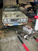
To show you the ropes, we’re documenting a real life swap and walking you through it. While a bit of an odd-ball, our victim, a ‘74 Datsun pickup that we decided to call “Walter” fit the criteria of being unique, somewhat cool (he has a classic Datsun 510 vibe) and practical (Walter is a cheap truck). And as a senior benefit, Walter’s ’74 birthdate qualifies him for a smog exemption in the state of California; something worth considering when searching for your own candidate. Throughout this article we’ll occasionally refer to ol’ Walter as a “620”, a term commonly used by Datsun enthusiasts derived from the truck’s chassis code “PL620”.
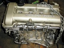
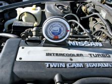
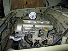
For the other half of the equation, we selected a naturally-aspirated RWD SR20DE (sourced from a JDM Nissan Silvia/180SX). While it was tempting to go with a turbocharged SR20DET variant, our goal was to play on Walter’s classic style with a set of ITB’s (individual throttle bodies) on open velocity stacks. There’s something crazy sexy about the looks and sound of an engine running open velocity stacks. Hopefully, this might help ol’ Walter out with his game.
CAN IT FIT?
When people ask us if a certain crazy swap can be done, our standard answer is “sure, if you have enough time and money”. Since most of us don’t have a lot of time or money, the key is to keep things simple. When choosing a swap, be realistic about it. Consider your skill level, the ease of fitment and how much fabrication is involved. A couple key things to consider are the physical dimensions of the engine relative to the engine bay and the clearance around key components which cannot easily be moved, such as crossmembers, steering/suspension components, the firewall and the transmission tunnel. While some of this stuff is difficult to precisely calculate, taking a measuring tape down to a local self-service junkyard can often give you a good idea if something might or might not work. When dealing with clearance to steering components, take a look at where the car has its steering system mounted. Some steering systems mount to the rear of the front wheels/knuckles, while others mount to the front side. This usually determines the location of the oil pan sump. With some engines, the manufacturer might offer both a front sump and a rear sump pan for use in different vehicles; this could give you some options. Unfortunately, in other cases such as our RWD SR20DE, the front sump is the only factory option (that we know of). Start by doing your homework. Odds are that if you’re thinking about the swap, someone else around the world is thinking about doing it or has already done it. Often times, these conversions are documented on the internet, providing a wealth of information.
BUDGETING FOR YOUR SWAP
Along with the planning comes working out a budget. Once you have a number, add about 30 percent to the budget for all the little trips down to the store for hardware, chemicals/fluids and the miscellaneous parts you forgot to account for. Thirty percent might sound high, but the last thing you want to do is run out of money and not be able to complete your project. Custom swaps are much more complicated than simple bolt-on swaps and typically have extra hidden costs.
OUT WITH THE OLD AND IN WITH THE NEW
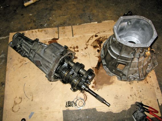 | We built a hybrid transmission for the swap, mating an SR20 bellhousing with an R32 Skyline GTS -T transmission (from the RB20DET engine).
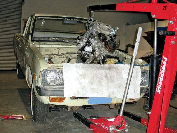
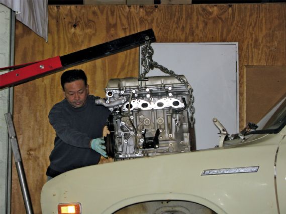
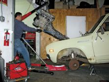
Once you have your new engine and transmission in-hand, it’s time to yank out the old one. This is the easy part. It’s like the demolition stage when remodeling a house. Tearing things apart is easy, the challenge is getting things back together.
Be prepared to drop the engine into the bay a few times. To keep things simple (and lightweight), a good idea is to strip off any unnecessary parts such as the intake and exhaust manifolds, alternator, starter, etc. Not only is it easier to drop in a stripped down motor, but it also gives you more room when it comes to fabricating your mounts. Just be sure to test fit all the other parts for clearance to avoid any last minute surprises. Another trick is to leave the clutch off the engine. This will give you the option to mate the engine to the transmission inside the bay during the test fitting stage; this trick comes in handy when dealing with a long engine and a short engine bay.
 | The engine and the transmission were installed individually. The two components were later bolted together in the engine bay. Not having a clutch on the back of the motor for test fitting made the task much easier.
FITTING THE ENGINE
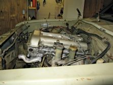
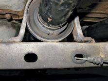
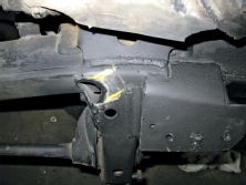
In the case of Walter the 620, we had to find a way to gain clearance between the exhaust header and the frame. Space between the header and the steering shaft was equally scarce. After considering all our options, we made the decision to position the engine slightly over toward the passenger’s side of the vehicle. Clearance on the intake side wasn’t much of an issue because our ITB setup is very compact and there is no steering shaft to deal with.
 |
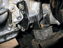
On the initial mock- up, you can see how the fitment with the factory mounts was pretty close.
|
On the initial mock- up, you can see how the fitment with the factory mounts was pretty close.
As a general rule, try positioning the engine as far back and as low as reasonably possible. This will help with the front-to-rear weight distribution and the vehicle’s center of gravity. Also take note of the position of the engine relative to the centerline of the front wheels. For handling, the more weight you can get behind the front wheels the better. That said, use common sense and avoid mounting the engine so low that the oil pan bangs against every rock in the road. In Walter’s case, we also had to watch the clearance between the oil pan and the center link for the steering system, this limited how far rearward we could go with the engine.
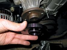
The next thing to consider is the mounting angle of the engine. On the RWD SR, the valve cover comes tipped at an angle (from side-to-side) from the factory. Don’t get fooled by this and try to straighten it out; you want to set the oil pan level, not the valve cover. If you know what vehicle your engine came out of, it’s a good idea to check the stock mounting angles and attempt to duplicate them. This is also true for the front to rear angle (how far the engine tilts back). Not only does the tilt of the engine affect the oiling system, but also the angles for the driveshaft. We’ll talk about this more in detail when we get around to the driveshaft section.
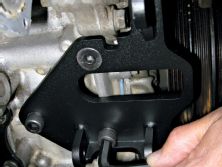
MOUNTING THE ENGINE AND TRANSMISSION
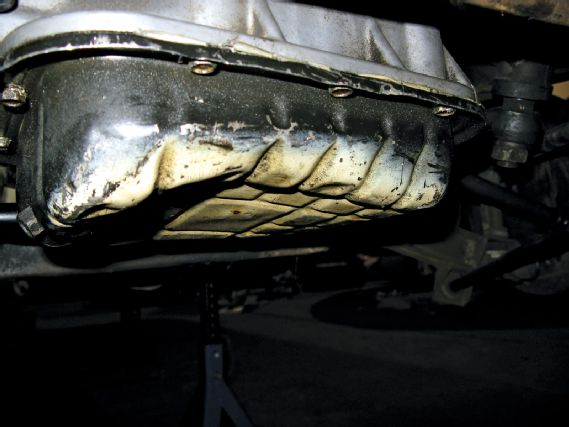 | The RWD SR20 valve cover naturally chills with a tilt to the side. Don’t try to correct this; instead, set the oil pan level to the ground.
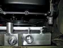
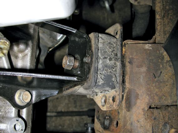
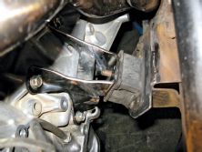
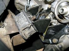
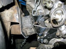
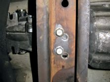
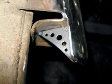
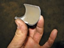
Each swap has its own unique mounting requirements. With some cars, you can simply swap out the engine crossmember and everything bolts right in. In other cases, you have to get a bit creative. With Walter, things lined up reasonably well from the start. That said, we still had to lower the front of the engine and extend the mounting pads on the frame forward. Modifying the mounts required taking a section out of the metal engine brackets and then welding the two halves back together (see images).
Throughout the mid 80’s and into the 90’s, Nissan used theFS5W71C transmission behind many of its RWD engines; including the JDM SR20DE(T), USDM 240SX and the four-cylinder Hardbody trucks. Knowing this, and the fact that the bellhousings on these transmissions are interchangeable, can help when doing a custom Nissan engine swap. When we began this venture, we had an engine but no transmission. To solve this issue, we took a short drive to see Marco Vargas at the SR20 STORE in Gardena, CA. As you can tell from the name of his shop, this guy knows everything about SR20s and stocks all of the common parts (as well as some rare ones). After we explained what we were doing, Marco was nice enough to let us take measurements off the various transmissions he had at the shop. As we sized up the SR20DET transmission, we realized the shifter would sit a little far back to work with Walter’s bench seat. So instead of buying a complete transmission, we settled for an SR bellhousing, salvaged from a blown transmission. Doing a bit more research, we learned that the RWD R32 Skyline RB20DET transmissions might work, but finding one was the issue. Lucky for us, we’re pretty well-connected in the Los Angeles area and finding rare parts is not always a problem. After a few days and a lot of calls, we located our holy grail at GARAGE BOSO, the home of Formula D driver, Ross Petty. Nevermind what parts we used, the point is that often times searching for the right transmission/bellhousing combo can lead to a better fitment. For more information on how to swap a Nissan bellhousing, be sure to check out our step-by-step tech article also featured in this issue.

HEADER AND EXHAUST
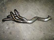
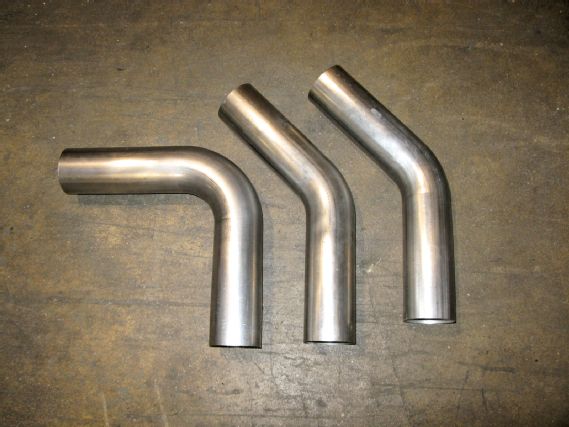 | These mandrel-bent stainless elbows were sourced from Performance Tube Bending in Irwindale, CA.
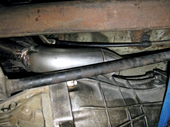
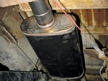
Attempting to fit a JDM header from a RHD Nissan Silvia/180SX into a LHD 620 was no simple matter. Sure we could have used a stock cast manifold, but what’s cool about that? The three areas of conflict were the steering shaft, the frame/crossmember and the suspension torsion bar. Shifting the engine slightly toward the passenger’s side of the vehicle solved the clearance to the steering shaft. To get around the torsion bar, we chopped the header right after the collector and snaked around the bar using mandrel-bent pieces of stainless steel tubing sourced from ptbtubebending.com. Clearing the frame required some grinding and notch made out of a piece of 1.75" DOM rollbar tubing. The rest of the exhaust was fabricated out of more mandrel-bent pieces and flanges sourced from PTB which terminates at a stainless steel Magnaflow muffler. Each swap is different but expect to either bust out the welder of find a competent muffler shop in your area.
 |
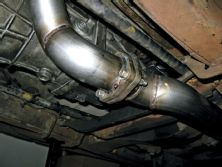
Snaking the header around the torsion
bar required several bends to be welded together.
|
Snaking the header around the torsion
bar required several bends to be welded together.
DRIVESHAFT
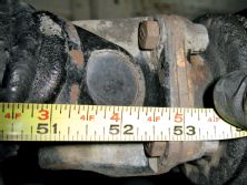
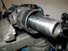
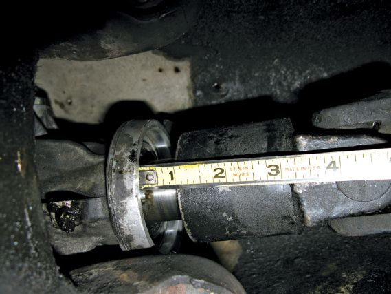 | Measuring out the length for a driveshaft is as
simple as spanning a measuring tape from the
rear seal of the transmission to the face of the
differential flange. If your differential doesn’t have
a flange (as depicted in this diagram) you should
measure to the centerline of the U-joint.
| Measuring out the length for a driveshaft is as
simple as spanning a measuring tape from the
rear seal of the transmission to the face of the
differential flange. If your differential doesn’t have
a flange (as depicted in this diagram) you should
measure to the centerline of the U-joint.
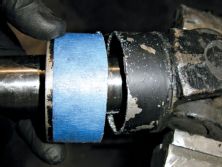
Creating a conversion driveshaft is not as difficult as people think. For the most part, it’s a matter of combining a transmission slip-yoke (for your new engine/transmission) with a flange that matches your rear differential. Before you bust out your hacksaw and MIG welder, keep in mind that there’s a big difference between a tube that fills the gap between your transmission and your differential and a properly designed driveshaft. For starters, unless you are a machinist you might not want to modify your own driveshaft. There are plenty of local driveshaft shops who specialize in this field. As a recommendation, we’d suggest contacting driveshaftshop.com. They have a huge selection of off-theshelf driveshafts for most common swaps and can work with you to create whatever custom driveshaft you need.
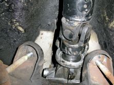
Calculating the length for your driveshaft is simple. In most cases all you need is a measurement between the rear seal of your transmission and the face of the flange on your differential. Work with your driveshaft builder on this; there’s not an industry standard and some shops like to do things differently. Keep in mind that if your vehicle has a live axle like our 620, the length and angles of the driveline will change as the suspension travels up and down. For this reason, all calculations should be made at your vehicle’s normal ride height (with the weight of the vehicle loading the springs).
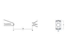
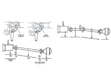
Calibrating the angles for your driveshaft can get a bit more confusing. To help break this down, we contacted The Driveshaft Shop (DSS) for some expert advice. Here’s what we learned: It’s all about the driveshaft’s “working angles”. To help explain this, check out the diagram above that we got from DSS. The image shows three measured angles along with two simple mathematical equations. Let’s start with the three angles; the transmission sits at 10 degrees, the driveshaft at 13 degrees and the differential at 16 degrees. To calculate the front “working angle”, take the driveshaft angle of 13 degrees and subtract the transmission angle of 10 degrees. Assuming you made it past the first grade, take 10 away from 13 to get 3 (degrees), the “working angle” of the front U-joint. Applying the same concept to the rear U-joint, take 16 degrees from the differential minus 13 degrees from the driveshaft and you should get 3 degrees for the rear “working angle”. Using a little logic, we can see that the working angles can be modified by tweaking the angles of the transmission and differential. As for a target working angle, the textbooks say 3 degrees for both the front and back. Unfortunately, in the real world, that doesn’t always happen. Each car is different and some don’t give you much to work with. As a rule of thumb, try to keep the working angles at 4 degrees or less and within one degree of each other. Again, these are ideal numbers to shoot for; what you can get away with will depend on each car. Frank from DSS gave us this little tip: Measure the factory angles prior to starting the swap, and then try to duplicate these angles with the new setup. The Driveshaft Shop has more information on calibrating driveshaft angles available on their website or you can call their tech line if you have specific questions.
SECOND FITMENT
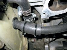
HEATER HOSES
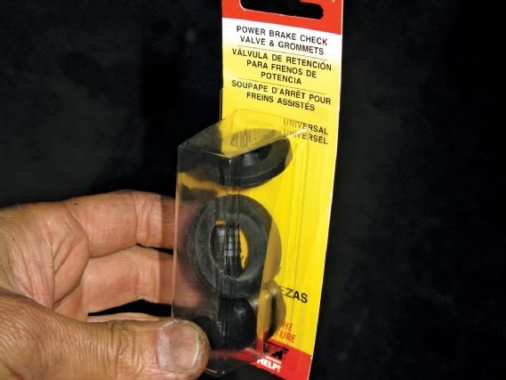 | We used a pack of grommets from a power brake system for
our heater hoses.
| We used a pack of grommets from a power brake system for
our heater hoses.
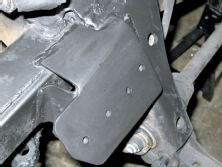
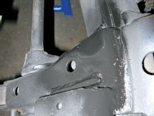
With the initial fitment done, it’s time to pull the engine back out and tidy things up. For us, this meant bracing up the extensions on the mount pads, cutting a notch in the frame/crossmember to clear the header, and installing the clutch. As you can see in the pictures, the added touches to the engine mounting pads not only added strength but also gave it a more finished look. For the notch, we started with a piece of DOM rollbar tubing, ground out a half circle in the frame, and used the half-pipe of tubing to fill it in. Welding this type of cap in not only looks cleaner but it boxes in the hole to help restore the rigidity of the frame. After touching up the welded areas with some flat-black paint, the clutch was installed and the engine was dropped back into the chassis—this time together with the transmission. The header could then be permanently installed and the fitment around the notch was re-checked.
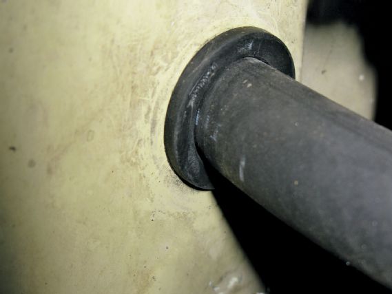 |
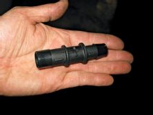
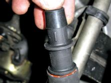
Sometimes you just have to shop around and
be creative.
|
Sometimes you just have to shop around and
be creative.
Adapting heater hoses for a swap is not difficult, it’s just one more of those pesky little time consuming items on the to-do list. Generally speaking, it’s a matter of piecing together different hoses, couplers and adapters. Unfortunately, this usually involves multiple time consuming trips to the auto parts store. In our case, we used a combination of 90 degree molded hoses coupled with a pair of 3/4" to 5/8" hose adapters. The reason we needed the adapters was to step up from the truck’s 5/8" heater core to the engine’s 3/4" fittings/lines. If you’re a bit OCD, you can usually get the guys at your local parts counter to let you dig around their inventory and sometimes find a single hose that fits or can be cut down to work. This could get you around the ghetto-look of all the pieced together clamps and fittings.
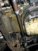
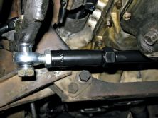
STEERING COMPONENTS
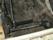
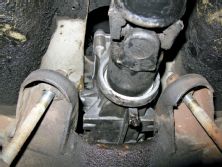
As mentioned in the beginning of this article, steering components can sometimes get in the way of your swap. If you’re lucky, the oil sump on your donor engine will clear everything in the new chassis. Unfortunately, in the real world, that doesn’t always happen. In addition to the oil sump, donor engines that have the exhaust exiting to the driver’s side of the vehicle are prone to clearance issues with steering shafts and other steering related components. While modifications to either the steering system or the exhaust components are possible solutions, they typically require extra hours of fabrication. With Walter, we ran into two steering related clearance issues. The first was between the header and the steering shaft, which we resolved by shifting the mounting position of the engine and the second was between the oil pan and the centerlink. Resolving this issue required fabricating a custom steering link that could be flipped to the bottom side of the pitman and idler arms. We’ve covered the fabrication for this part in detail and broke it off into its own little tech story which can be found at the end of this tech section. Note: most newer vehicles will be equipped with a rack and pinion steering system and may have a different set of problems.
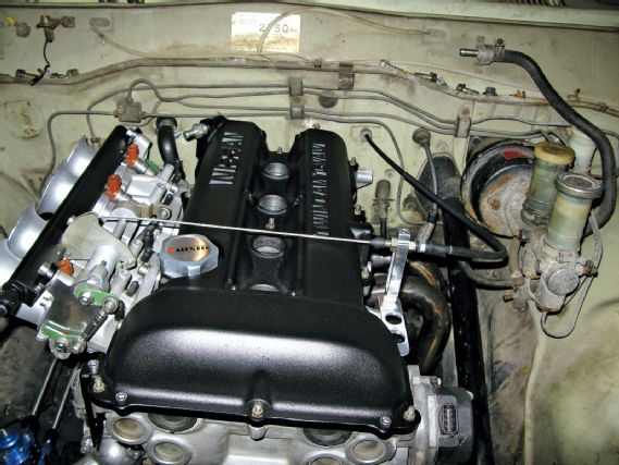
THE INTAKE SYSTEM
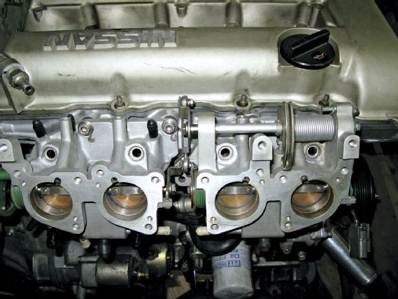 | These individual throttle-bodies come stock on the JDM Pulsar GTIR
SR20DET engine. While the ports line up with the S13 SR20 head, some
of the mounting holes have to be re-drilled.
| These individual throttle-bodies come stock on the JDM Pulsar GTIR
SR20DET engine. While the ports line up with the S13 SR20 head, some
of the mounting holes have to be re-drilled.
Clearance issues on the intake side of the engine don’t tend to be as common. If your engine places the intake manifold on the driver’s side of the vehicle your odds of having issues are much higher. But even then, components such as the brake booster and master cylinder tend to be far enough away that they typically don’t collide with the intake plenum. Of course, there are plenty of exceptions and custom engine swaps tend to bring out the worst of them. When working on your swap, common intake related mistakes to avoid are: positioning your cold air inlet too low (prone to sucking up water and hydro-locking the engine), mounting a mass airflow sensor too close to the inlet of a turbo (air turbulence can screw with the MAF readings), or simply being sloppy on the plumbing and allowing unmetered air to enter the system (via vacuum leaks). In our case, we took the uncommon route of installing individual throttle-bodies on an SR20. To many, this makes no sense because the SR20 is one of the best engines for boosting on the planet (arguably so). But hey, to each his/her own. Walter’s an old guy and a bit limited in the braking and turning departments. What he lacks in performance and good looks, he makes up in style—and that’s what we’re playing upon. Bang for your buck, this setup doesn’t really make sense. While the GTIR individual throttle-bodies can be sourced for cheap, be prepared to drop some coin on a stand-alone computer to run them. A decent set of cams will wake the engine up but short of plumbing in some happy gas, this naturally aspirated setup won’t stack up to its boosted counterpart.
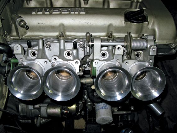 |
Not much is cooler than an open velocity stack on the end of each
throttle body. These stacks were added by drilling and tapping mounting
holes in the throttle-bodies.
|
Not much is cooler than an open velocity stack on the end of each
throttle body. These stacks were added by drilling and tapping mounting
holes in the throttle-bodies.
CARBURETOR TO FUEL INJECTION
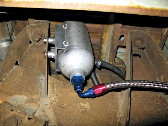 | Installing a surge tank is a good way to protect your engine from
fuel starvation when converting from carburetion to fuel injection.
| Installing a surge tank is a good way to protect your engine from
fuel starvation when converting from carburetion to fuel injection.
Converting from carburetor to fuel injection seems pretty simple. Just add a high pressure electric fuel pump and add a return line right? No, not really. We’re not saying that you can’t get an engine running like this, but there are deeper matters that should be considered. For starters, high pressure EFI pumps push fuel much better than they pull it. That’s one of the reasons why most factory EFI pumps sit inside the fuel tank. When you mount one externally, not only do you need to mount it close to the tank but you also need to set it lower than the tank’s outlet so that gravity can feed it. While this layout is feasible for some cars, it doesn’t work for others (due to space limitations). The second and often overlooked issue is the design of the fuel tank. Older carbureted cars tend to have poor baffling in the fuel tank, allowing fuel to slosh around during heavy acceleration, cornering and braking. As fuel sloshes away from the pick-up point, the pump sucks in air and fails to deliver fuel to the engine. Carbureted engines compensate for this with a small fuel reserve in the fuel bowl, but EFI setups don’t have this feature and a lack of fuel at the pump translates to a lean condition at the engine. On production vehicles, manufacturers typically design fuel tanks with internal pumps surrounded by a small box which serves as a fuel reserve. One option is to steal these parts from an EFI tank and adapt it to your carbureted fuel tank or you can build an external surge tank. That’s what we did for Walter. To see how to do this, check out the detailed how-to article also included in our Project Car Garage Universal Tech section.
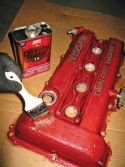
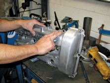
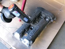
ENGINE DRESS-UP
By nature, custom engine swaps are unique and tend to draw attention. People are going to want to see your engine so you might want to make it look presentable. If you’re short on time (or lazy like us), put more of your efforts into the top half of the engine. Powdercoating the valvecover goes a long way. Bead-blasting aluminum parts will make them look new. It’s all labor intensive but if you do things yourself, the cost can be very low. We’ve covered DIY powdercoating before so we won’t go into it in this article. The main thing to know is not to prep your valvecover with a bead-blaster. Media can get trapped in the baffles where it waits to fall into your engine. Instead, use paint remover, a soft wire brush and some sandpaper–the old fashion way.
THROTTLE CABLE
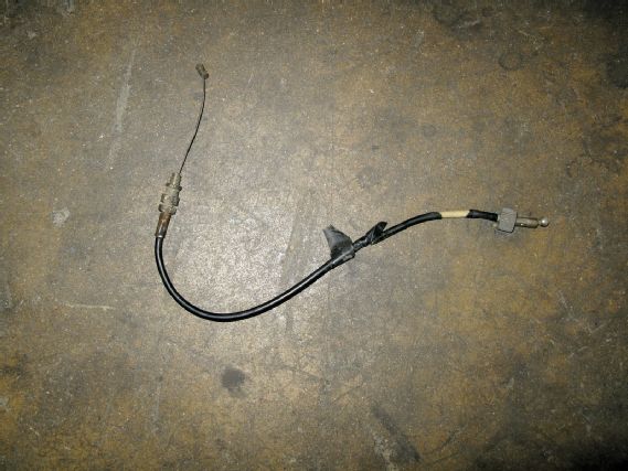 | Using the truck’s cable, a newer Nissan cable
and some simple DIY steps, we created a custom
throttle cable for our ITB setup.
| Using the truck’s cable, a newer Nissan cable
and some simple DIY steps, we created a custom
throttle cable for our ITB setup.
Figuring out how to connect a donor engine to the throttle pedal often stumps the mind. It’s really not that hard and there is no reason to over-think the equation. Most of us started out wrenching on bicycles where we learned how to modify brake cables. Throttle cables work in a similar fashion so let’s consider this mod simple enough for a 12 year-old to do. For you older folks struggling to grasp the concept, we’ve broken things down in yet another Project Car Garage Universal Tech article; please be sure to check it out.
 |
The Ins and Outs of a Custom Engine Swap
|
The Ins and Outs of a Custom Engine Swap
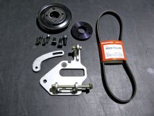
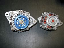
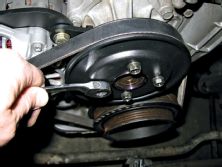
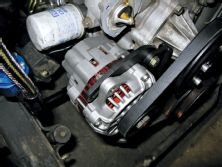
ALTERNATOR CLEARANCE
If your vehicle has a narrow engine bay, you could run into a clearance problem with your alternator or other belt-driven accessories. For us, the 620’s frame was wide enough, but the top of the idler arm got in the way of mounting the stock SR20 alternator. Knowing that the Datsun Roadster’s have a similar (but worse) clearance issue, we contacted Michael Spreadbury of Spriso Motorsports in Corvallis, OR for the solution. Having been in a similar bind as he pioneered the SR swap into the Roadster, (over ten years ago), Michael Spreadbury embarked on a mission to find the smallest alternator that could work on an SR20 engine. After scouring through junkyards and countless bins of alternator cores, he surfaced with a pea-sized unit from a Subaru Justy. Ok, it was bigger than a pea, yet only 2/3 the size of the SR alternator. From there, it was a matter of creating a bracket to get it mounted. As word got around about the swap, a demand surfaced for information as well as specialty parts for the conversion. Ten years later, the bracket has been perfected, now designed in AutoCAD, laser cut and TIG-welded. Spriso Motorsports continues to grow and develop new parts for this specialty market. The point is, that necessity is the mother of invention and if you have a particular need, check around because somebody else out there has probably been down your same path. In cases like our alternator bracket, a solution was already available; we just had to find it. For more information about Spriso Motorsports and the products it offers, be sure to check out spriso.com.
RADIATOR AND FAN
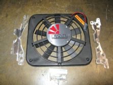
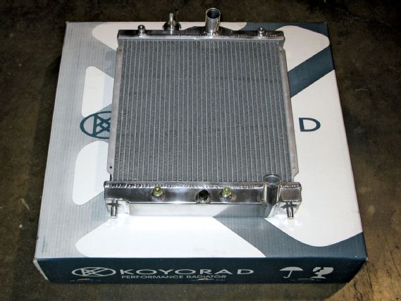 | Finding a radiator to work with our swap was not an easy task. In the
end, we decided on a ½ size Koyo aluminum racing radiator, designed
for the Honda Civic.
| Finding a radiator to work with our swap was not an easy task. In the
end, we decided on a ½ size Koyo aluminum racing radiator, designed
for the Honda Civic.
Robbie recently cranked up the thermostat on the shop’s water heater and I now burn myself every time I turn on the faucet. Applying this “bigger and better” mentality to your swap sometimes works but it’s not the answer for everything. When it comes to the cooling system, efficiency is more important than size. Radiators work by moving air through the core which in turn cools the fluid inside. While sizing your radiator is important, ensuring proper air flow through the radiator core is equally important. To do this, block off any gaps around the sides of the radiator to direct the flow of air through the core and not around it. Keep in mind that at highway speeds, the fan doesn’t really do much—it’s all about the ram air effect created by moving the car through the air at higher speeds. For the stop-andgo, that’s when the fan comes into play. When selecting a fan, consider the quality, air flow rating and physical dimensions. A fan shroud greatly adds to the efficiency of the fan by expanding the surface area of the radiator core being used. Anytime a shroud can be used, use it.
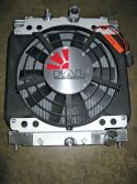
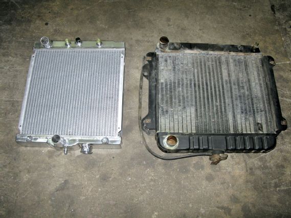 | As you can see here, the ½ size Civic Koyo radiator is not far off in overall
dimensions from the truck ’s original piece
| As you can see here, the ½ size Civic Koyo radiator is not far off in overall
dimensions from the truck ’s original piece
A common problem on engine swaps is the length of the engine relative to the engine bay. In many cases such as our 620, space can be limited between the radiator and the front of the engine. If at all possible, stick to using a puller fan (pulls air through the back of the radiator) as opposed to a front mounted pusher fan. While pusher fans can work, they are not as efficient and can even block airflow to the radiator core. Getting a puller fan to fit in a tight space can be tricky, but there are products on the market designed to help you out. For our swap, we started with an aluminum Koyo racing radiator, designed for the Honda Civic. Being a half-size design, it closely matched the dimensions of the trucks original radiator. The other nice thing about this unit is its aftermarket support. Since it’s made for a Honda, Flex-a-lite offers an off-the-shelf low profile fan specific for the application. Our only challenge now is to mount the radiator to the truck and find a way to connect the hoses. Unfortunately, after test-fitting the unit in the truck we’ve realized that connecting the hoses will be easier said than done. We have no one to blame for a fitment issue. This radiator was not designed to work with an SR engine or a Datsun truck. It’s up to us to make things fit. We’ve run out of time and our deadlines won’t wait for us to complete this swap. We’ll return fully equipped with a large hammer, a saw and a welder and give you a follow up report in the next issue.
Also remaining on the to-do list is the wiring to get this heap we call Walter back on the road. We’re still exploring our options but due to the individual throttle-bodies, it will most likely involve wiring in a stand-alone ECU. Stay tuned, we’ll be right back.