 Installing an AEM EMS-4 - Stand Alone and Deliver
Tools Needed: Ratchet, metric sockets and combination wrenches, Phillips and a flat-blade screwdriver, wire cutters, wire crimpers, utility knife, heat shrink tubing, wire ties, soldering iron, electrical solder
Difficulty Level: 4.5 out of 5
Parts ListStreet Price AEM EMS-4 Universal Engine Management System$759 AEM EMS-4 Full Universal Harness Kit$240 Total$999
When it comes to plug-and-play engine management systems, AEM has led the way with its EMS and EMS Series 2 systems. As the popularity of the EMS has grown, so has the demand for a universal standalone EMS. To fill this demand, AEM recently released the EMS-4, a highly-capable standalone system that is not only compact, shock and weatherproof, but also budget-friendly. Although designed with Powersports in mind, this mini-version of the Series 2 EMS can run almost any 4-cylinder engine and best of all; the tuning can be done through the user-friendly AEMTUNER software. With a street price of roughly $800, this system is a great alternative for race cars, off-road vehicles and custom engine swaps, especially with older vehicles which don’t require the extra bells and whistles that the EMS Series 2 has to offer.
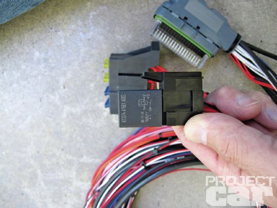
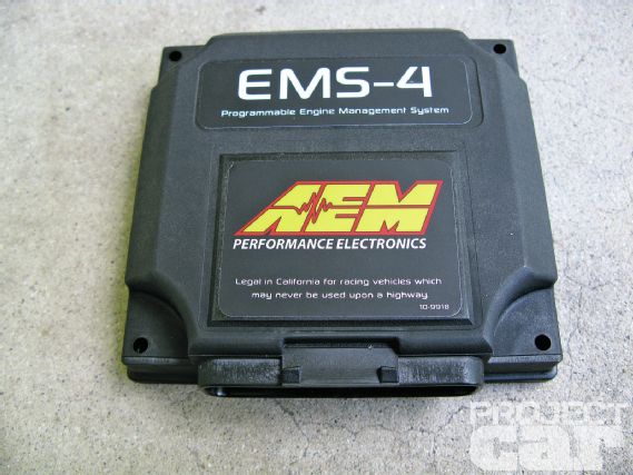 | 01 Don’t be fooled by its compact design; the AEM EMS-4 offers 8 MB of internal data logging, 4 injector drivers, 4 coil triggers, Mag or Hall cam and crank inputs, knock input, 8 general purpose inputs and outputs and much more.
Keep in mind that the EMS-4 is not for everyone. Being a universal system, it must be custom wired either using the EMS-4 full universal harness or the basic plug and pin kit. While the labeling and grouping on the full harness makes it much easier to wire the system, don’t expect to get a full step-by-step instruction sheet for your individual application. This is designed to be installed by an experienced installer and the instructions assume that you know your way around a fuel injection system. For most people, it’s much simpler to start out with a plug-and–play EMS or Series 2 EMS system. But if you happen to be working on a less than popular engine or car that does not have a plug-and-play option available; the EMS-4 is a great bang-for-your-buck alternative.
 | Installing an AEM EMS-4 - Stand Alone and Deliver
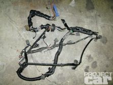
Being in need of an engine management system capable of running the ITB setup on our SR20 swapped Datsun 620, the EMS-4 seemed to be a great option. While we could have started out with a full factory SR20DET harness and a Series 2 EMS, we thought it would be cool to tailor fit a new harness for the engine and at the same time get rid of all the unnecessary wires and connectors. More importantly, we wanted to save a few bucks and to gain some hands-on experience with the EMS-4. As always, we’ve documented the entire installation and are here to bring you the step-by-step process. Our goal is to give you a better idea of what’s involved in the installation and at the same time, educate you on the basics of a fuel injection system.
The Cam and Crank Angle Sensors
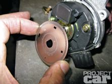
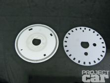
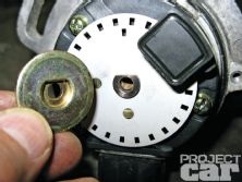
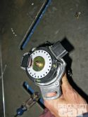
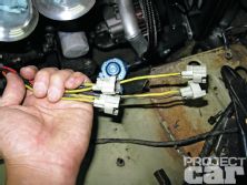
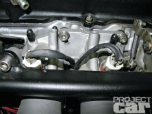
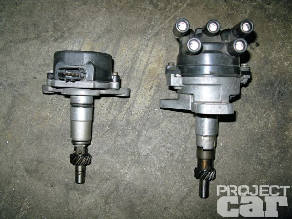 | 07 Here we have the distributor from a naturally-aspirated RWD SR20DE on the right and a CAS (crank angle sensor) from a turbocharged SR20DET on the left. Since we wanted the benefits of a DIS (distributorless ignition system), we’re ditching the distributor and running the CAS. The SR20DE distributor actually has an optical pick up like the CAS and can run the system if equipped with the correct timing wheel, but aesthetically, it’s not too pleasing.
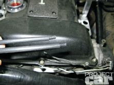
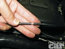
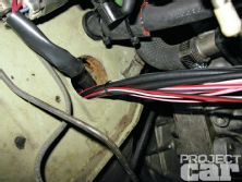
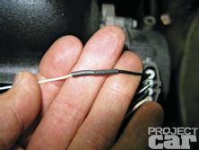
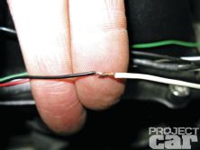
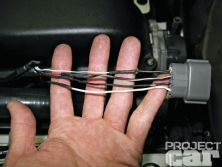
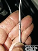
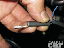
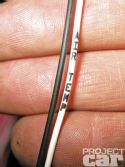
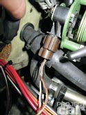
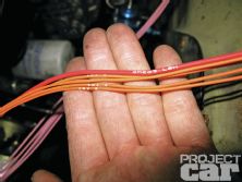
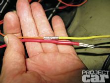
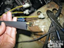
 | 16 After stripping the insulation, you should see the shielding wire. Under that you’ll see a thin metal shield that looks like aluminum. The shielding is there to ensure that a clean electrical signal reaches the ECU.
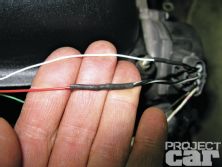
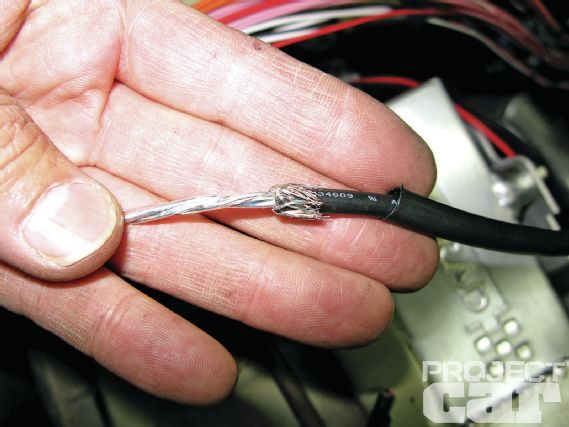
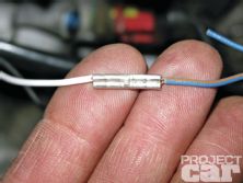
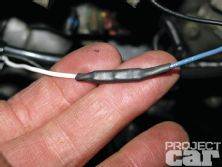
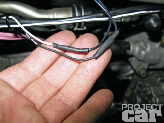
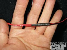
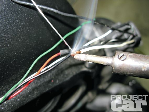 | 21 Slip a piece of heat shrink tubing over the wire, connect the two wires, heat the wire with the iron and then melt the solder on the heated wire.
The Engine Coolant Temperature Sensor
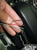
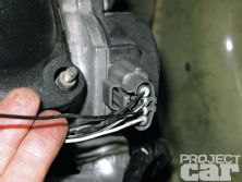
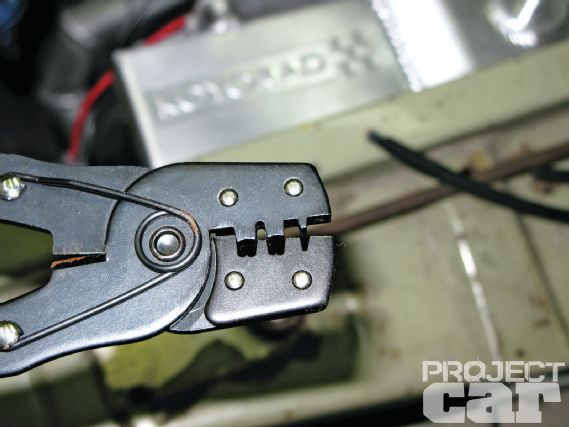 | 26 While many will argue that soldering is best, we believe that each method has its pros and cons. One of the downsides of soldering is that the connection can fail due to vibration; being in the engine bay, the harness will see plenty of it. We’ll be the first to admit that a poor crimp connection is the worst culprit for failures, but if you work carefully and use proper equipment, crimping can yield an extremely reliable connection. In the second picture, you can see the teeth on our crimpers. This is a relatively inexpensive crimper designed for non-insulated connectors.
The Intake Air Temperature Sensor
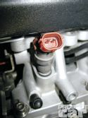
 | 28 Next, we’ll be installing an AEM IAT (intake air temperature) sensor. As implied by its name, the IAT sensor reads the temperature of the air entering the engine and sends a signal to the ECU. The ECU uses this data to fine tune the air/fuel mixture.

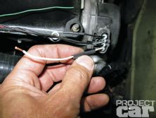
 | 30 Like with the ECT, wiring the IAT was a snap. In this case, polarity doesn’t matter so just connect the two wires from the harness to the two wires on the sensor.
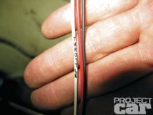
The Throttle Position Sensor
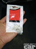
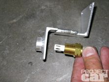
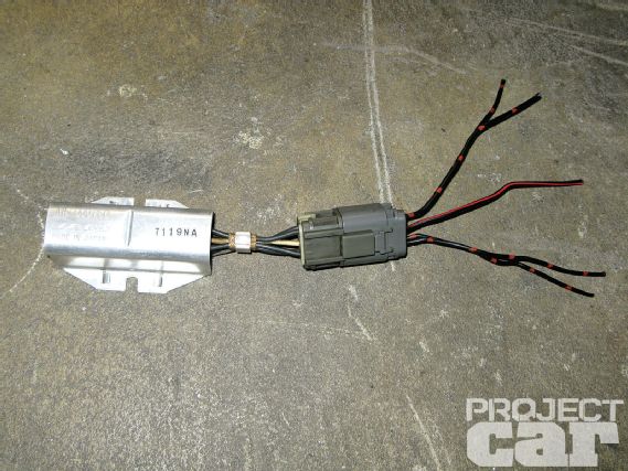 | 36 The solution for running low impedance injectors on a high impedance system is to add a resistor pack. These can commonly be found at a wrecking yard since many 90’s era cars used them.
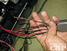
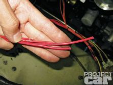
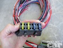
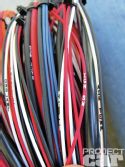
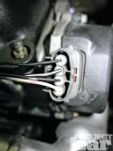
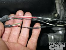
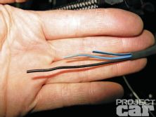
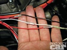
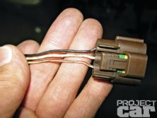
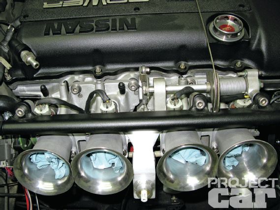 | 45 The injector wires come labeled from 1 to 4. While you have the option to match the wiring to the firing order on your engine it’s simpler to wire it to its corresponding cylinder (1-4 from front to back). The phasing can then be set through the software to match the firing order of your engine.