 | Installing AEM EMS-4: Continued
The Ignition
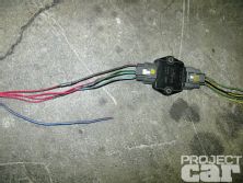
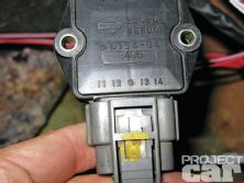
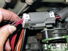
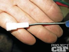
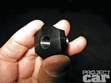
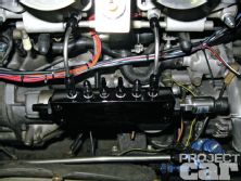
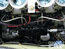
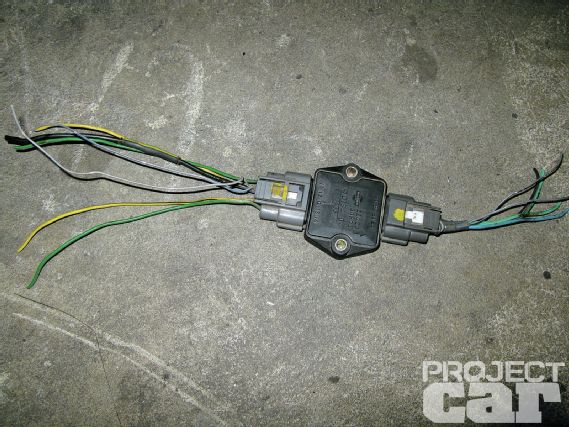 | 46 As previously mentioned, we decided to ditch the stock SR20DE distributor and upgrade to an SR20DET DIS system. In order to do this, we had to wire in an igniter. This one came from a ‘95 USDM Infiniti Q45, which interchanges with the JDM SR20DET. If grabbing one from the junkyard, don’t forget the pigtails.
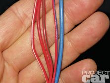
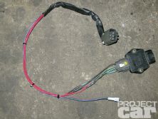
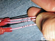
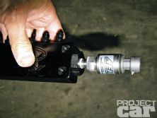
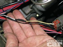
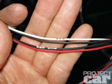
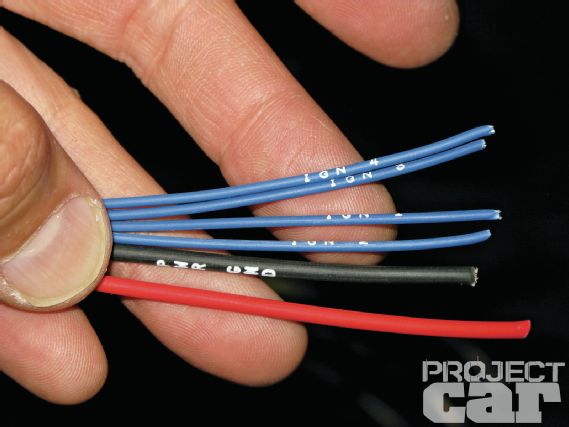 | 49 Wiring the input side of the igniter is just as simple. The EMS-4 harness provides a wire for each coil (IGN1 through IGN4) and even supplies the power and ground wires.
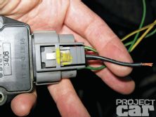
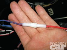
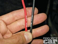
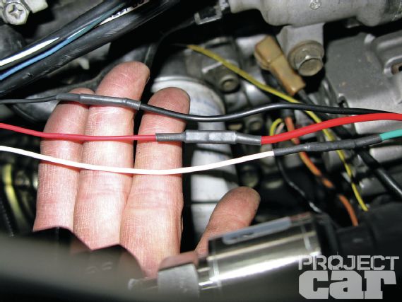
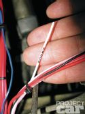
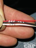
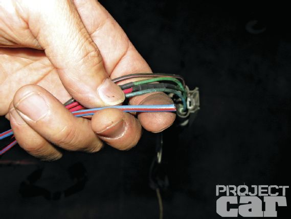 | 51 The blue/red wire feeds power to the coil packs. It’ll connect with the red “COIL PWR” wire from the harness.
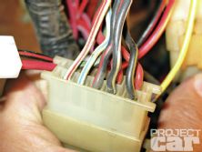
The Power Center
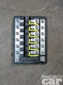
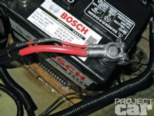
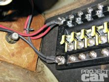
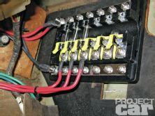
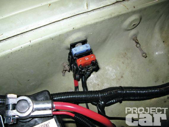 | 58 As an added measure of safety, a gigantic fuse was added inline to protect the circuit.
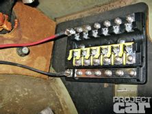
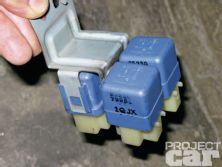
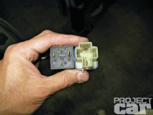
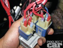
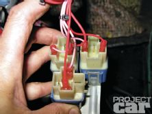
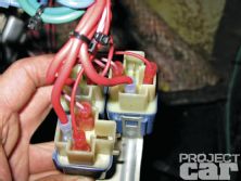
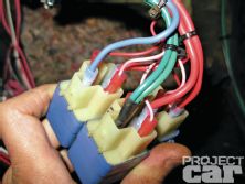
The Output Relays
The Map Sensor and Vacuum Manifold
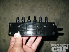
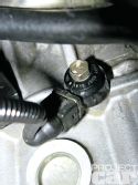
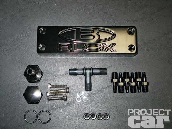 | 70 Because our open velocity stack ITB setup does not have a plenum, getting a stable vacuum signal for the MAP sensor and the brake booster can be challenging. Not having the time to fabricate something, we decided to try out BLOX’s new vacuum distribution block. The fact that it was designed for distributing vacuum on a Honda B-series engine didn’t stop us. After all, the fun part of building cars is finding ways to adapt and improvise.
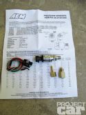
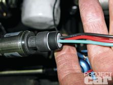
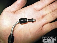
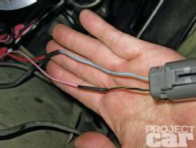
 | 75 Connect the red VCC wire to the sensor’s red wire, the black sensor ground wire to the black wire and the white signal wire to the green wire.
The Optional Sensors
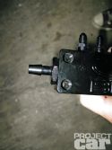
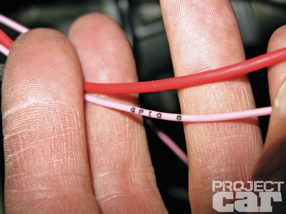 | 84 The EMS-4 is capable of running the factory Nissan idle control valve through one of its PWM capable GPIO outputs (GPIO 5 through GPIO8). Here we’ve got the pink wire for GPIO8 connected to the black/yellow wire leading to the factory AAC (auxiliary air control) valve and the red “SPARE POWER” wire running to the valve’s blue power wire.
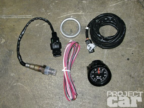 | 86 The harness makes it super simple to wire in an AEM wideband kit (shown in the second image) as it provides power, ground, AFR input and sensor ground. The only two remaining wires to connect are for 12V switch power and illumination.
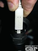
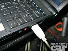
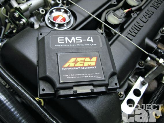
Connecting The EMS-4
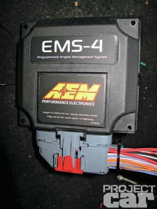 | 87 With the harness fully wired, it’s time plug in the ECU.