It doesn’t matter if you drive a GM, Ford, or Ram diesel truck—if it was built after 1993, it has a turbocharger under the hood. If you’re currently driving one of the new-generation clean-diesel light-duty vehicles, be it a car from Volkswagen, BMW, or Audi, or an SUV from Jeep, Mercedes, or Porsche, you too have a turbo tucked away under the bonnet. While turbocharger technology has come a long way in a relatively short amount of time, the basic principles remain the same.
Every turbocharger design—whether it’s single or compound, small or large, with fixed or variable geometry—shares the same function and principles. The job of a turbo is simple enough in theory, and that is to increase the density of the air that is available to an engine. Engine power output is dictated by the amount of fuel that an engine can burn, and the amount of fuel an engine can burn is directly proportional to the amount of oxygen that is available. By increasing the amount of available oxygen (air density), more fuel can be consumed by the engine, thereby increasing power output.
Getting More Air Into An Engine
To get an idea of how a turbocharger compresses air, we can simply follow the airflow. Fresh air is drawn into the engine through an air filter, which removes impurities that can cause damage to the turbocharger or other vital engine parts. Once through the filter, air is routed to the compressor side of the turbo, which, as the name implies, compresses the air. Most turbocharged diesels are fitted with a charge-air cooler (aka intercooler) of some type, and as the compressed air leaves the charger it is routed through a cooler, which in turn lowers the temperature of the compressed air, adding further density to the air charge.
After passing through the charge-air cooler, the compressed air moves through the intake manifold, cylinder head, and into the cylinder for combustion. Once fuel has been added and combustion completed, hot gases are expelled into the exhaust manifold during the exhaust stroke. The high-temperature gas then continues on to the turbine side of the turbocharger. As the hot exhaust gases circulate around the turbine, a pressure and temperature drop occur, causing the gases to expand. The energy produced by the expansion of the spent exhaust gas is then harnessed by the turbine, which provides the power necessary for it to drive the compressor wheel. Finally, the exhaust is routed out of the turbine housing, through any applicable aftertreatments, and exits the tailpipe, thus completing the cycle.
Airflow Diagram
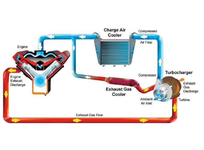
| Turbo Airflow Diagram
The Short Version
Exhaust gases are routed into the turbine housing and spin the turbine wheel, which turns the common shaft shared by the compressor wheel, sucking air from the intake and pressurizing it using the compressor housing, pushing more air into the cylinders than a naturally aspirated diesel.
Compressor/Turbine Diagram
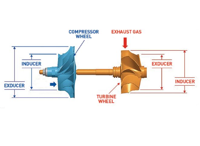
| Compressor Turbine Diagram
Terminology
Aftercharger: A radiator placed between the turbo-compressor outlet and the engine intake manifold used to cool the intake charge, which is heated by the pressurization of the turbo (also called an intercooler or charge-air cooler).
Airflow (cfm): A measurement of how much air and exhaust is able to flow through the turbo; airflow is measured in cubic feet per minute.
Area/radius (A/R): The ratio of the cross-sectional area of the exhaust-turbine inlet/compressor outlet divided by the radius from the center of the turbo wheel to the center of the cross-section. Differences in compressor A/R do not affect performance much. However, a large turbine A/R will allow big power gains at high engine rpm but will cause turbo lag at low speeds.
Backpressure: A buildup of pressure in the exhaust that prevents the free flow of new exhaust gases and slows the speed of the turbine wheel. Backpressure that builds after the compressor in the intake can cause the wheel to suddenly stop spinning (surge).
Ball bearings: Steel or ceramic bearings mounted inside a circular housing or cartridge that surround the turbo shaft, used in place of less expensive brass-sleeve bearings (journal bearings). Ball bearings are thought to provide about 25 percent quicker turbo spool up and require less oiling pressure than conventional journal bearings.
Blow-off valve: A valve between the turbo and the intake manifold that vents air to avoid turbo surge when a preset pressure limit (boost) is surpassed.
Boost: The intake pressure created by the spinning of the compressor wheel inside the housing. Measured in pounds per square inch over the normal atmospheric pressure (normally about 14.7 psi at sea level).
Centersection: The cartridge between the exhaust and intake sides of the turbo that houses the turbo shaft and contains the bearings, oiling system, and water-cooling system (where applicable).
Compound turbos: Two or more turbos that feed into each other in series to build high boost pressures. Air is sucked into a larger turbo (also known as the atmospheric or low-pressure turbo) and is then compressed into a smaller turbocharger (high-pressure), which compresses the already-compressed air a second time, leading to very dense air and high pressure ratios.
Compressor wheel: The intake side wheel that utilizes blades to bring in fresh air and compress it against the compressor housing backplate.
Downpipe: The exhaust pipe that leads from the turbine outlet to the exhaust system.
Impeller: Another name for a compressor wheel.
Inducer: Where flow enters the turbine or compressor wheel. Most common measurement used in turbo sizing nomenclature. Example, a 75mm turbo S400 refers to the compressor wheel inducer being 75 mm in diameter, whereas the wheel’s exducer is 100 mm.
Shaft: What travels through the centersection and connects the turbine wheel to the compressor wheel.
Shaft play: Condition in a worn turbo in which the shaft is allowed to move (other than spin). A small amount of radial play (side to side) is acceptable. However, large amounts of axial play (back and forth) indicates trouble. An abnormal whine, chirp, or scraping sound can be a sign that a turbo is suffering from shaft play.
Spool: Another term for turbo boost. A turbo is spooled up when it is creating boost in the intake manifold.
Trim: The ratio of the inducer area divided by the exducer area.
Turbine wheel: The wheel that is spun by exhaust gases that pass through the fins and into the housing before dumping into the downpipe.
Turbo lag: The time it takes for a turbo to spool up after the throttle has been applied.
Twin turbos: A system using two turbos of identical size mounted in parallel. Example: a turbo feeding each bank of a V-8 engine.
Variable-geometry turbo (VGT): A turbo that uses variable vanes or a sliding nozzle to alter the volume inside the exhaust housing to maximize turbo speed at low engine rpm. Also known as variable-turbine geometry (VTG).
Variable nozzle: A sliding nozzle in the exhaust side of the turbo that can reduce the volume around the turbine fan blades to increase turbo rpm at low engine loads.
Variable vanes: Adjustable blades that route exhaust gases directly into the turbine wheel at low engine rpm to increase boost on tap at low speeds.
Wastegate: Bypass that diverts excess exhaust gases away from the turbine once a preset boost level is reached in the compressor side of the turbo. It can be built in to the turbine housing (internal) or can be separate from the turbo housing (external).
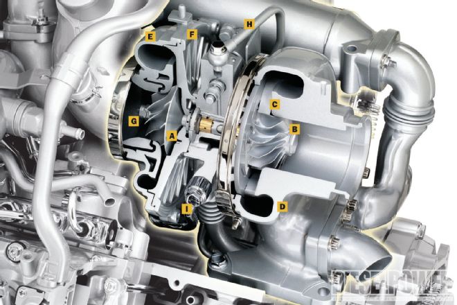
| A. Compressor wheel
B. Turbine wheel
C. Variable vanes
D. Exhaust turbine housing
E. Compressor housing
F. Backplate
G. Turbo shaft
H. Oil-supply line
I. Water cooling line
Diesel Pickups: A Brief Turbo History
Early diesel pickups utilized a single, fixed-geometry turbo, while later models employ a variable-geometry aspect. Starting in 1989, Dodge fitted the 5.9L Cummins with a single, fixed-geometry Holset turbo and, with the change to the 6.7L engine in 2007½, made the move to a variable-geometry turbo, also from Holset.
GM began turbocharging its diesel engines with the introduction of the Detroit Diesel 6.5L in 1992, as a single BorgWarner charger found its way onto most engine applications. Following suit, the original Duramax, the LB7, received an IHI fixed-geometry charger. All the subsequent Duramax engines have been fitted with a single, variable-geometry unit from Garrett.
The last truck manufacturer to offer a turbo option was Ford. For the ’93 and ’94 model years, its previously naturally aspirated 7.3L V-8 IDI diesel was available in both non-turbo and turbocharged form. Since that time, Ford has made what some would call the most radical changes in regard to the turbocharger technology found within the Power Stroke engine family.
Beginning with the 7.3L in 1994 (’94½ MY), Ford originally fitted the Power Stroke with a single, fixed-geometry Garrett turbocharger. Along with the introduction of the 6.0L Power Stroke in 2003 came a single variable-geometry unit, also from Garrett. In 2008, Ford changed the game when it introduced the 6.4L Power Stroke with a compound turbo setup from BorgWarner that hadn’t previously been used by an OEM. Four years later, with the launch of the 6.7L Power Stroke, Ford upped the ante again when it paired the new engine with an all-new turbocharger from Garrett: a single-sequential turbo, which utilizes a single turbine and two compressor wheels on a single shaft.


