| servicing Aqua Hot Systems Heating Efficiency aqua Hot System 450 De
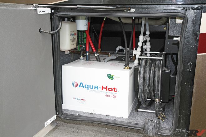
Hydronic heating systems are very popular in diesel-powered, Class-A motor homes. A hydronic heating system utilizes a diesel burner and an electric heating element to heat a boiler that then circulates boiler antifreeze throughout various zone within the coach to provide heating via small heat exchanges. In addition, domestic hot-water heating needs are met by this type of system, so it performs dual duty and replaces your hot-water heater as well as the furnaces.
There are many benefits to hydronic heating. The diesel burner is more efficient than propane-fired furnaces and the diesel burner operates off the vehicle’s diesel fuel tank, so no additional runs to get propane are required. The larger fuel tank also provides for a longer running time between refills. The electric heating element is incorporated so that you can use the campground electricity to assist in heating your boiler. Because there is no hot-water heater tank, the ondemand system will provide continuous hot showers without ever running out of hot water. All in all it’s a great system.
Like any mechanical system, eventually it will require service. The vast majority of the systems used in RVs are made by Aqua-Hot Heating Systems, so we’ll cover what’s involved with maintaining your Aqua-Hot system in order to keep it running at peak efficiency. Aqua-Hot recommends an annual service schedule, although this can vary, depending on how much you use your Aqua-Hot system throughout the year. Servicing the burner isn’t all that hard to do once you know the basic steps. It can be time consuming and having this work done by a service professional will cost you some money, which is mostly for their labor, not for their service parts. Exact service manuals for your particular model can be found on the Aqua-Hot website, but the Webasto burners used in these models are basically the same, so the service techniques will be virtually identical for all units.

| 01. AquaHot systems utilize a threebank control panel to switch on the diesel burner, electric heating element, or the engine preheater.
Getting Started
The annual service is, basically, replacing the fuel filter, replacing the burner nozzle, and giving the burner a good inspection. If the combustion chamber is sooted up, it should be cleaned at this time. While Aqua-Hot recommend’s an annual burner service, many field service techs agree that if the unit is burning fine, leave it alone. The annual recommendation is based upon average use. After so many gallons of diesel fuel have run through the fuel filter it will need replacement. Again, this will vary as to how clean your fuel was.
The burner nozzle is a finely machined orifice that is designed to spray fuel at a 60-degree cone and at a flow rate of 0.35 gallons per hour. This hole will erode over time just from passing fuel through it. The more fuel that passes through, the greater the erosion. When the hole increases in size your fuel flow rate will increase, resulting in a burner that runs rich, develops an unburned fuel odor, and may even smoke. If you don’t run your heating system that often, there may be no need to change the nozzle on an annual basis.
Conversely, if you use your system extensively you may need to perform this service more frequently. Remember that this service should be done as needed, not just because a piece of paper has one year printed on it.

| 02. Fuel filters need to be changed regularly to ensure the diesel burner gets a clean supply of fuel. Shutoff valves were added to this spin-on fuel filter assembly to prevent fuel dribbling when changing the filter.
Changing the Fuel Filter
Most systems use the Garber spin-on fuel filter, which can easily be removed with a standard oil filter wrench. Prior to spinning on the new filter, rub a little fuel oil on the gasket to prevent it from pinching and binding when you install the filter. You can use vise grip pliers to pinch off the fuel line to eliminate any drainage when the filter is being changed or you can add a petcock valve like I did.
Purging the Air from the Fuel System
When you switch on the diesel burner, the burner, the blower and the fuel pump will run for approximately 15 to 30 seconds. This is a purge cycle designed to blow air through the combustion chamber so that any hot spots can be cooled and any unspent fuel can be purged.
After the initial purge time has passed the burner’s computer will allow the fuel solenoid valve to open, and fuel will flow through the nozzle. At the same time the transformer will energize, sending a high-voltage current to the electrodes, which creates a spark, igniting the fuel. When it’s time to stop heating the boiler, the fuel solenoid will close and the burner flame will stop. The blower motor will continue to purge air through the combustion chamber for another minute or two in order to cool down the unit. It’s important to note that the electronic controller times and switches the various components within the burn cycle, but the fuel pump is constantly turning and pumping fuel whenever the blower is running. It’s just not atomizing it through the nozzle when the fuel solenoid valve is closed.

| 03. Once the cover is removed you’ll have access to the burner control module. The module slides off of the mounting grooves in the side of the burner motor. The two wiring plugs can then be removed and the controller set aside.
So, in order to purge the air from the fuel system, you just need to run the pump for a while. To do this switch on the diesel burner. Allow it to run for 5-10 seconds to initiate the pre-burn purge cycle, and then switch it off. During this time the fuel pump will attempt to pump fuel and return it to the fuel tank via the return line. If you listen carefully you will hear the motor sound change and bog down once the fuel finally gets to the pump. You may have to repeat this cycle a second time if all of the air has not yet been purged from the lines. You will need to have all of the air purged from the fuel lines if you want to test your burner’s operation or check the fuel pump pressure. Once the filter is changed and the purge complete, you can move on and tackle the burner itself.

| 04. The red petcock is a drain for the boiler antifreeze. If you bump it you’ll have a mess on your hands. I inserted a brass pipe plug in the end of the valve to prevent that from happening.
Removing the Burner
The burner access cover is held in place with four Phillips-head screws. Remove them and lift the cover off of the unit. You will now see the fuel lines entering the unit. One line is a supply line that comes from the fuel filter, which is connected to the fuel tank. The second line is a return line that sends unused fuel to the tank. The Webasto burner is a two-pipe system that constantly pumps fuel from the inlet to the return line and back to the tank. This is necessary to ensure bleeding any air out of the system after the tank has run dry or the fuel filter has been changed. The large black item is the Webasto burner. This unit contains the burner motor, ignition transformer, fuel pump, blower fan, fuel shutoff solenoid, nozzle, electrodes, and photocell sensor. All of this is stuffed into one compact unit.

| 05. Once the two retaining eyebolts have been loosened the burner motor can be slid out and rotated for ease of access to the nozzle end.
A silver controller box is also visible in this image and is attached to the left side if the burner. This electronic controller module controls the burner motor, fuel solenoid, ignition transformer, and photocell operations. It performs all of the timing and switching operations needed during the purge and burn cycles. The two larger round items at the bottom-left are the circulating pumps for the anti-freeze and the 4-inch square electrical box with the yellow warning label covers the 120-volt electric heating element.

| 06. An electrode gapping tool is included with every system. Slip the tool over the end of the nozzle to check the electrode gap.
Also, note the hose clamp around the rubber hose at the bottom of the burner. This is an air-intake hose for the burner that extends through a hole in the floor. It has a reputation for collapsing, which restricts the intake air to the burner and makes it run rich. It can be removed with no ill effects, but the electrical wiring and components in your housing are no longer shielded against intrusions by field mice. Many owners remove the hose and then attach a piece of 1/4-inch wire mesh screening over the hole to prevent this. In my case I just put some mesh inside the intake hose to prevent it from collapsing.
The burner assembly needs to be removed from the unit in order to service it. Begin by sliding the silver control box off the burner housing and unplug it. Next, remove the hose clamp that secures the air intake hose to the bottom of the burner. Finally, loosen up the two nuts that hold the burner to the boiler housing. Use a 10mm deepwell socket with some long extensions to access them. You do not need to remove the nuts. Just back them off to the end of the threads. The eyebolts will swing out of the way and you can slide the burner out of the boiler assembly. You do not need to remove the fuel lines when doing this. If you do, you just make a big mess. There is enough slack in the lines that you can pivot the burner so that the nozzle end is facing out and easily accessed for service.

| 07. The number one cause of smelly combustion is a worn nozzle. Be sure to hold the nozzle holder with a 3/4-inch wrench. Then place a 5/8-inch wrench on the nozzle to remove and replace it.
Electrode Adjustments
The electrodes need to be properly located or your burner will fail to ignite. Also, the gap needs to be placed just outside the fuel spray cone. Fortunately, an electrode gapping gauge is supplied. Generally this unit is found attached to the side of the burner and can be used simply by removing the screw. They are available online via the Aqua-Hot website if yours is missing.
To adjust your electrodes, slip the tool over the nozzle. The tips of the electrodes should rest in the notches that are cut into the gapping tool. If the electrodes do not line up, loosen the electrode retaining clamp bolt and move them to the correct position. When tightening the bolt, do not over-tighten it or else you may bend the clamping bar or even crack the ceramic insulator on the electrode. If that happens, you will need to replace the electrodes. During most annual services you will not need to adjust the electrodes. Once they are set in place they should stay put for a long time. Eventually the tips of the electrodes will erode away from the constant arcing. When these tips appear to have widened the gap beyond 1/8 inch, it is time to adjust your electrodes. If the gap is extreme you may need to replace them.

| 08. The swirler and burner tube slides right out of the boiler housing.
Nozzle Replacement
This is the No. 1 service point on the Aqua-Hot/Hydro-Hot system. The nozzle is the most critical item on any oil-fired burner. The nozzle itself is finely machined to spray a regulated amount of fuel in a pre-determined spray pattern. If even the smallest spec of dirt
enters the nozzle, it can plug the vanes or orifice and cause it to spray in an erratic pattern. It’s also just as critical to use clean practices when servicing the burner and handling the nozzle. Do not touch the tip of the nozzle, drop it, or allow dirt to get on the inlet screening.
To replace the nozzle, place a 3/4-inch wrench on the nozzle holder to prevent it from turning. Then place a 5/8-inch wrench on the nozzle and remove the nozzle by unscrewing it in a counter-clockwise direction. Carefully insert the new nozzle and tighten it using the two wrenches. Once it is tight, back the nozzle off one quarter of a turn. Then, retighten it. This reseating of the nozzle is necessary to ensure that the threads will properly seal and that no fuel will be leaking from the nozzle threads.

| 09. Clean the combustion chamber with a wire brush and shop vacuum to remove any soot buildups.
Cleaning the Combustion Chamber
A dirty combustion chamber is the final step in servicing your burner. The combustion chamber consists of an aluminum swirler and a steel tube. This unit slides into the boiler cavity and is easily removed by hand once the burner motor has been removed. Once the combustion chamber has been removed the boiler housing should be checked for any build-up of soot. A wire brush and shop vacuum are helpful in cleaning the chamber to restore it to peak efficiency.
Taking the Extra Step
If your burner is running well, all it will need is a filter and nozzle change. However, if these have been changed and the burner still is not running well, further testing and adjustment may be required. It can get very complex, and unless you want to do some serious work and remove the unit for bench testing, you would be best off having it serviced by a professional. However, there are three items that you can easily check to see if you need to go that far. These three areas are voltage, air intake, and fuel pressure.
Fuel pressure is easy enough to check when you are servicing the burner. You do need to get a fuel pressure gauge to do this. Aqua-Hot offers a fuel pressure gauge on its website. It’s a bit on the pricey side, but then most Aqua- Hot items are. I chose to make my own gauge and save some money. I did this by taking an old nozzle and drilling it out, tapping for 1/8-inch pipe threads, inserting a 1/8-inch pipe and air pressure gauge with a 0-to-200-psi range. That works just as well as the “official” gauge and saved me quite a bit of money. Even if you do need to purchase one, it will still be far less than paying a service tech to do this task for you.
The gauge is inserted into the nozzle holder, so the nozzle is removed and the pressure gauge is put in its place. You will need to place the burner assembly on its side in such a position so that you can see the gauge without handling the unit. When the fuel solenoid opens, the ignition will create a high-voltage spark across the electrodes; you don’t want to be handling the unit when that happens. You then switch on the diesel burner and watch the gauge. When the burner first runs it will begin a purge cycle. During this time the blower fan will push air through the combustion chamber, purging it of any unused fuel. After maybe 15 to 30 seconds the fuel solenoid will open, allowing fuel to flow through the nozzle. Once this happens the needle on the gauge will suddenly swing over to the 145 psi position. If your gauge shows 145 psi, your pressure is correct and you can go and switch off the burner. It will then enter another cool-down cycle whereby the blower fan continues to run before coming to a stop. Normally the fuel solenoid valve will engage quickly and the fuel pressure will rise smartly. The same holds true upon shutdown but when the pressure gauge is connected the fuel will be locked inside the tube with no way to bleed out so your gauge will not return to zero as fast as it rose. In fact, you may
need to loosen the threads in order to bleed off the pressure locked up inside the gauge assembly.

| 10. Replacing the nozzle with a fuel pressure gauge is necessary to verify that the fuel pump is putting out proper fuel pressure.
If the pressure needs adjustment there is a small screw on the side of the fuel pump that can be turned to adjust the fuel pressure delivered to the nozzle. You only need minute adjustments to bring it to 145 psi so take it easy when performing this. You’ll need to do this while the burner is running so you will need to remove the high voltage wires from the electrodes or transformer in order to prevent voltage from jumping around and giving you a real good sting. If the pressure is not coming into tolerance or is gradually dropping when running you’ll have other issues that will need to be dealt with. You may be sucking air into the fuel lines, you may have a bad fuel pump strainer screen, or a bad fuel pump. Either way it’s time for some higher level service. You’ll need to refer to the service manual or have it dealt with by a professional at that point.
Your Aqua-Hot system needs to have adequate voltage present. If the voltage is low your burner motor will run slow. If that happens you won’t get enough airflow through the chamber to provide clean burning and your fuel pump may not develop full pressure due to lower rpm. To check for proper voltage take the leads from a voltmeter and test for adequate voltage at the hot terminal on the controller board. The Aqua-hot requires voltage between 11.5 and 14.0 volts DC.

| 11. A slotted screw is found on the side of the fuel pump to allow adjustments to the fuel pressure.
Any flame requires both air and fuel in order to burn. To have a clean burning flame you need to have the proper ratio of air to fuel. Your Aqua-Hot diesel burner is no different. The air intake tube attaches to the base of the burner. The base includes a baffle that can be rotated to increase or decrease the size of the air intake port. The baffle is held in position by a small Phillips head locking screw.
When fully open, the port will be one half of circle, in other words 180 degrees. It is possible to fully close the opening but not possible to open it more than 180 degrees. The systems are generally preset at the factory to a 90 degree opening, which is the middle of the adjustment. Sometimes this can vary and you may find a red stripe that marks the position of the baffle adjusting screw for its initial opening position. If you open this up farther you will get more air and if you reduce the aperture you’ll get less air. In order to properly adjust this opening you will need some sophisticated exhaust gas sampling equipment, which is covered in the service manual but is beyond the scope of this tutorial. For all practical purposes just leave it alone.
If you keep your hydronic heating system in tip-top shape, you’ll have many hours of clean burning operation and maximum heating efficiency, while minimizing your diesel-fuel consumption.

| 12. A volt meter can be used to check for proper voltage at the main control board. If the voltage is low the burner motor will run at a slower rpm and you’ll notice smoke from the exhaust due to lack of adequate combustion airflow.