Warn M8000 Winch Breakdown - Four Wheeler Magazine

Warn M8000 Winch Breakdown - Winch Wear warn M8000 Winch winch Full Photo 9307917

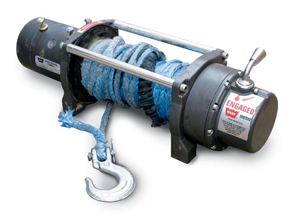
We'd used our venerable Warn M8000 for about six years or so, and it had never let us down. We had rescued stuck trucks, righted rolled-over rigs, and extracted ourselves from rocky notches and waterfalls too steep to climb. Though our winch hadn't seen a lot of mud, it had been submerged underwater a number of times in creek and wash crossings. It had also seen years of fine desert dust that had surely worked its way into our trusty companion.

But in recent years, we'd noticed a little more noise coming from the drum assembly, so we decided it best to do a little inspection and maintenance as needed. You can find an exploded parts diagram in your original Warn manual, along with a parts list. If not, you can find them on Warn's Web site, in the "Replacement Parts" section. Once you identify any seals, gaskets, or other worn parts you want to replace, they can be ordered from your local Warn dealer for quite reasonable prices. Along with that, you'll want fresh grease for the internals.

We tore down our M8000, then cleaned, inspected, lubed, and reassembled it in a few hours. The job required only common handtools and was fairly straightforward. Many Warn models should be similar in this process. Follow along as we revitalize our winch.

PhotosView Slideshow 1. To start the disassembly, we removed the detent screw that secures the clutch engagement lever and removed the lever, metal retainer, and O-ring seal. 2. Next, the 10 socket-head cap screws were removed from the end housing, freeing it and the ring gear that houses several planetary gearsets. 3. With the end housing and ring gear separated from the drum support, you can see the hex shaft that transfers drive from the motor on the opposite end of the winch to the small 12-tooth sun gear in the end housing. 4. Next we removed the splined drive gear from the end of the drum assembly. The two socket-head cap screws were removed and the drum support was separated from the two tie-rods. 5. With the end of the drum assembly exposed, we found the first drum bushing. These appear to be made from a nylon-type material and are used to support and locate the drum in the side plates. 6. Here you can see the drum support on the motor end (left) and the drum assembly. Inside the drum is a brake assembly that mates to the coupler on the motor shaft. Do not remove the brake or apply any lubrication to the brake. 7. Next, we removed the second drum bushing from the motor-side drum support. Here is where we found a good bit of accumulated dust and aged grease. 8. The last part removed was the motor coupler. We checked this piece for any signs of cracking or damage and made sure the spline fit was still snug to the splined motor shaft. 9. Grasping the end of the motor shaft, we wiggled it to check for any play or looseness in the bearing. We found none, so we stopped disassembly at this point. 10. Inside the end housing is a bronze bushing which supports the small sun gear. We checked for excessive play between the two and found they still fit close. On some Warn winches, this bushing can be replaced in the housing. 11. Massive gear reduction is obtained through the use of three planetary gearsets that reside in the end housing. We cleaned ours in solvent and checked for loose or damaged gear pins and worn teeth. 12. The end housing has the sliding ring gear that is actuated by the clutch lever. This gear moves to engage the drum for powered use or to disengage and allow it to spool free. PhotosView Slideshow 13. A hex shaft is used to transfer power from the motor drive to the sun gear in the end housing. We checked for any excessive looseness between the shaft and the inner hex inside the gear. 14. For gear lubrication, Warn recommends using either Molylube 1 or Aeroshell 17 (or its replacement, Aeroshell 33SM) grease. We used Aeroshell 17, an extreme-pressure synthetic grease with wide temperature use range designed to prevent surface corrosion or seizure. It is available from aviation suppliers. We found it online at Pike Oil Company. 15. With all our parts cleaned and inspected for wear or damage, we were ready to begin reassembly. We applied a dab of grease to the end-housing bushing and a light coating of 20-weight oil on the inside of the end housing and outside of the sliding ring gear before reinstalling it in the housing. The beveled spline ends on the sliding gear should be towards the back of the end housing. 16. The first new drum bushing was lightly greased and pressed into the motor-side drum support. We applied a little grease to the motor shaft splines and slid the motor coupler back in place. 17. The drum assembly was installed and the second drum bushing installed in the other drum support plate. Each bushing has a small alignment slot. 18. We closed up the drum area and secured the drum support to the tie-rods with the two socket-head cap screws. Check that the drum spins smoothly at this point. 19. A little grease was applied to the splined drive gear, and it was inserted in the end of the drum. The hex shaft was replaced in the drum as well, fitting it into the hex end of the brake assembly. 20. Then the small sun gear was lubed and slipped into the bushing in the end housing. 21. The two smaller planetary gearsets were placed into the gear housing. Warn recommends that these assemblies be liberally greased but that the end housing not be packed fully with grease. On top of these goes the thrust washer (step-side up in this photo). 22. The largest planetary set fits on top of the thrust washer, followed by the large ring gear whose splines mate to the raised area on the face of the end housing. 23. The assembled end housing is reinstalled on the drum support and secured with the 10 screws. It's necessary to again align the ring-gear splines and the bolt holes for this attachment. The holes align every other screw hole, or every 72 degrees. Finally, the clutch lever and its seal and retainer are reassembled back onto the housing. The lower end of the lever is aligned in the sliding ring gear to operate the Free/Engage modes. 24. With the winch back together, we renewed the winch rope and installed a new abrasion guard from the guys at Rockstomper. Our winch was quieter again and ready to tackle whatever the trail would throw at us.