If there were a vote for the most misunderstood automotive component, we're willing to bet the automatic transmission would rank pretty high, and the torque converter itself possibly higher still. OK, so it's kinda like a clutch for an automatic, but how does it work? And, what do stall speed and lockup mean, exactly? How do you choose the ideal torque converter for your project or driving style?
Perhaps we should start with the basics of how a converter works. It is essentially a modified fluid coupling that, like a clutch, allows the transmission to be separated from the engine, so the latter can still run while the car is stationary but allows power to be transferred when the car is in motion. Unlike a regular fluid coupling, however, a torque converter multiplies torque when there is a difference between input and output speed, similar to a reduction gear.
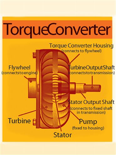
A torque converter consists of three major internal components: the pump, turbine, and stator, as well as transmission fluid. The housing of the converter is bolted to the engine's flywheel, and the fins of the pump are attached to the housing. This is a centrifugal pump, throwing fluid outward as it spins. This creates a vacuum that draws more fluid in at the center. The fluid then enters the turbine, which is connected to the transmission via the output shaft, so the trans starts to move the vehicle when the turbine starts to spin.
When the fluid exits the turbine, it is moving in the opposite direction to that of the engine and the pump. It is the function of the stator, which is located in the center of the torque converter, to redirect the fluid before re-entering the pump. The stator is mounted on a fixed shaft but has an internal one-way clutch, since it is required to freewheel at certain operating speeds.
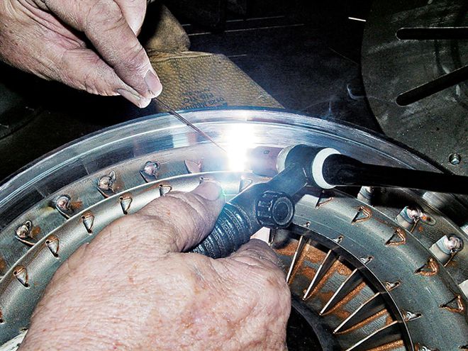 Phoenix Transmission Products' TIG brazes the bowl fins that have been bent to alter the stall speed. By brazing each fin individually, they stay in their intended position. Unbrazed fins can work loose or bend back under fluid pressure.
A torque converter has three stages of operation: stall, acceleration, and coupling. Stall is when the transmission is in gear, but the brakes prevent the car from moving. At stall, the torque converter can produce maximum torque multiplication, called stall ratio, if sufficient input power is applied.
The acceleration stage sees the car moving but a relatively large difference between pump and turbine speed, where the converter will produce torque multiplication that is less than what could be achieved under stall conditions.
Coupling is when the turbine reaches roughly 90 percent of the speed of the pump. There is no more torque multiplication, and it would be at this stage when a lockup clutch would kick in. Lockup converters have an internal lockup clutch that will lock the two halves of the torque converter together, eliminating any slippage where the engine and trans cannot physically operate at the same speed. This, in turn, eliminates any wasted power and so improves fuel efficiency by as much as 65 percent.
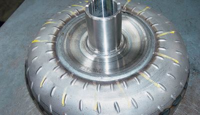
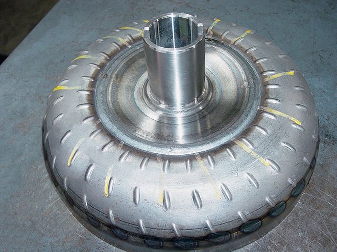
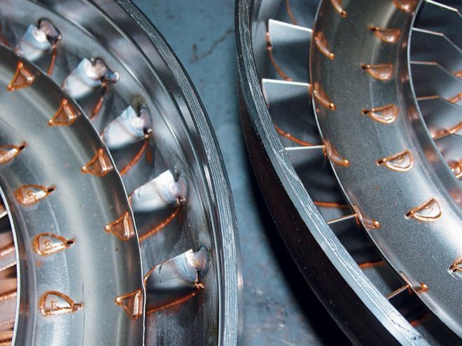 The bowl on the right shows stock fins and furnace brazing. The bowl on the left shows the modified fin angle and additional TIG reinforcement.
As for stall speed, Greg Ducato, of Phoenix Transmission Products, explained that "a torque converter is like a clutch. Imagine when a clutch is fully released, and you get all the power from the engine. That's stall speed. A 2,500 stall speed doesn't mean you need to rev the motor to 2,500 rpm for the vehicle to move." What it does mean in this case is 2,500 rpm is the limit at which the converter will hold back the engine speed if transmission output is prohibited. By disallowing further gain, the increase in engine rpm "stalls." The speed at which stall occurs with a given converter is a function of engine-peak torque.
You can roughly check your converter's stall speed by putting the car in Drive, pressing firmly on the brake, and depressing the throttle fully for a couple of seconds. Stall speed will be the maximum rpm shown on the tach. Of course, the tires may spin, as the engine will likely overcome the brake system's ability to hold them back. This method is referred to as brake stall speed, which is lower than true stall speed, but it'll get you close enough, though it's not recommended.
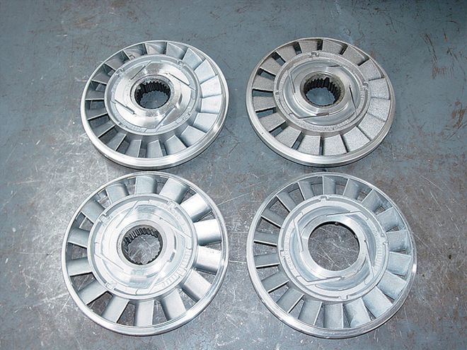 These are four different stators used in the 245mm converter to alter stall speed and torque multiplication. Note the differences in fin angle and window proportions. Dozens of different stall speeds can be achieved by using the right fin angle on the bowl and the right stator combination. Experience will allow the builder to select the right combination based on the particulars of your car and its intended use.
A number of factors should be taken into consideration to determine what stall speed is suitable for your project, such as engine-peak torque, the shape of the engine-torque curve, vehicle weight, rearend ratio, and cam specs. Weight and resistance has a great bearing on stall speed. According to Greg, "A 2,500-rpm stall speed converter in a T-bucket will probably stall around 1,800 rpm, but put the same converter in a pickup and that'll go up to around 2,800 rpm." With so many variables, arm yourself with as much information about your vehicle as possible before contacting a torque converter or transmission specialist.
The maximum amount of torque multiplication is dependent on the size and geometry of the blades in the turbine and stator, and it's generated only when the converter is at or near the stall phase of operation. Typical stall torque multiplication ratios range from 1.8:1 to 2.5:1. There will always be a trade-off between maximum torque multiplication and efficiency. High-stall ratio converters are usually relatively inefficient below the coupling speed, whereas low-stall ratio converters tend to provide less possible torque multiplication.
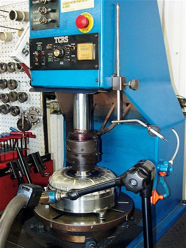 This automated converter welder positions both converter covers for perfect alignment while being welded together. This machine also holds critical endplay tolerances during this operation.
While torque multiplication increases the torque at the turbine output shaft, it also increases slippage inside the converter, raising the fluid temperature and reducing overall efficiency. This is why the internal parts and characteristics of a converter must be matched to the intended vehicle's specs. It should be noted that lower stall converters limit internal heat production, the biggest killer of any transmission.
Heat isn't the only cause of failure, though, and sudden applications of power in high-horsepower vehicles can break the stator clutch or deform or break the turbine or pump blades. Prolonged excessive loads, very high rpm, or hard launches can distort, or balloon, the housing, even rupturing it in extreme cases.
One aspect of converters we haven't talked about so far is sizing. Zack Farah at Gear Star Performance Transmissions explained why some converters are larger than others and how two different-size converters can have the same stall speed. "Two different-size converters can have the same stall speed, but their efficiencies will vary greatly," he said. "A converter pump will tend to have a higher efficiency when its blades have a positive angle to them, as this feeds the most fluid to the turbine. The more fluid you feed the turbine, the harder it pushes on it and the more torque is delivered to the transmission.
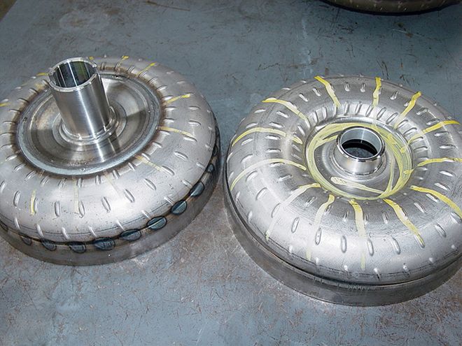 The converter on the left has an anti-balloon plate added, while the one on on the right has a stock-style cover. The plate helps the converter resist flexing and expansion in the thin hub area under extreme conditions. These plates come in various diameters and thicknesses depending on the application and are recommended for high-horsepower applications, especially with a power-adder like N.O.S. or forced induction. Phoenix uses antiballoon plates on all of its 245mm converters.
"For a 12-inch converter that normally stalls at 1,600 rpm to be converted to a 2,600-rpm stall, the pump blades can be bent back to a negative angle to feed less fluid to the turbine. This means the pump will have to turn more rpms to force the turbine with the same amount of fluid, and efficiency will drop off somewhat.
"A 9-inch converter stalls higher, because it generates less fluid by virtue of its smaller size. It takes more stall to achieve the same amount of hydraulic force as a larger 12-inch converter. The 9-inch is more efficient in high-stall applications, as the pump blades maintain a positive pitch. So, in essence, by bending the blades in a 12-inch converter, it turns into a heavy, inefficient, higher-stall converter in comparison to the smaller version. This is why Gear Star uses special pump and stator combinations to achieve high efficiency along with highstall peeds in its Stealth 12-inch converters."
This advice about not bending the blades would seem to contradict Phoenix Transmission's practice of doing exactly that, but Phoenix technicians rebuild and modify stock converters for specific applications, whereas Gear Star manufactures new units. As with most things, I guess there's more than one way to achieve similar results.