The first-generation Mustang has been on the road long enough that many have been restored a second or third time. Often, these restorations are cosmetic in nature and the drivetrain and suspension are only given a quick once over to ensure safety. Otherwise, little was made in the way of improvements for better performance, handling, or braking. Today it is a different story. As these first-generation classics are being driven more, owners want better driving manners, real brakes that can stop in modern traffic, and more.
Upgrading the suspension and braking on a first-generation Mustang doesn’t have to mean high-end weld-on systems with rack-and-pinion steering and so forth. You don’t want stone stock suspension bits, either. They will be new and tighten up the suspension, but they offer stock-like handling—not something to write home about. Some of the best “bang for the buck” suspension upgrades are direct-replacement pieces, such as tubular control arms, adjustable strut rods, larger diameter antisway bars, and so forth. You can update your suspension (and brakes, too, if you like) with basic hand tools in your own garage on a Saturday.
Total Control Products (TCP) has built a solid reputation in the Mustang hobby for offering no-compromise, high-quality suspension solutions, including four-bar rear suspensions with coilover shocks, and coilover front suspensions that eliminate the traditional coil spring. These systems work, but are overkill for some enthusiasts and are difficult to install. TCP has answered those enthusiasts’ needs by offering complete bolt-in direct-replacement front and rear suspensions. Up front, TCP offers its Coil-Spring Suspension system, which features tubular upper and lower control arms (optional offset upper arm for improved camber gain), performance coil springs, and bolt-in VariShocks.
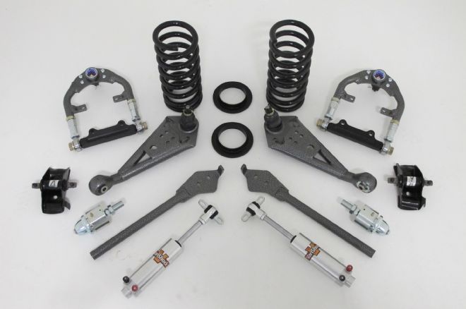

The setup uses stock mounting points and allows your car to gain a lower center of gravity, a higher roll center, and precise control of the spindle’s travel. Options include single- and double-adjustable shocks, offset upper control arm, antisway bars, and forged spindles. For our 1966 Mustang hardtop project we’ll be adding on the optional double-adjustable VariShocks, TCP antisway bar, and offset upper control arms.
At the rear, TCP offers a simple suspension system made up of performance mid-eye leaf springs, a bushing and shackle set, leaf-spring plates, and bolt-in VariShocks. Options are many, including adjustable shocks, antisway bars, torque arm, and Panhard rod systems, and more. Some of these rear suspension pieces can be had via various staged systems. For our 1966 Mustang hardtop project, we’ll be using the base Stage 1 leaf-spring system with double adjustable VariShocks.
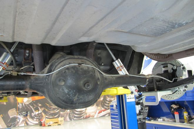
While our suspension is broken down for updates, we’ll be updating our Mustang with performance disc brakes from Master Power Brakes. And we plan to wrap the brake package in a performance wheel and tire upgrade that improves the Mustang’s connection to the road while still looking vintage classy. Although we’re using a lift in our tech center, you can easily handle the removal and installation steps outlined here with jack stands and a floor jack.
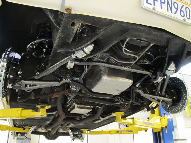
01. We’re beginning with the front suspension upgrades on our hardtop. Generally, you could remove the complete spindle and brake package together. However, we’re adding disc brake so we broke down the removal process into steps, removing the old drum setup first. Note, we’ve already separated the tie-rod end from the spindle and loosened the upper and lower ball joint nuts.
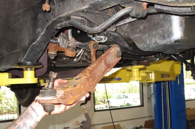
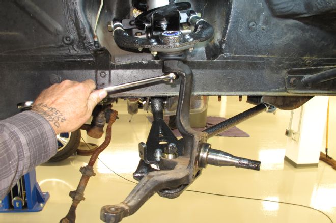
02. After removing the spindle and setting it aside for reinstallation later, the lower control arm and strut rod assembly were unbolted next. Again, you can remove the lower arm and strut rod together to save a few minutes of wrench time.
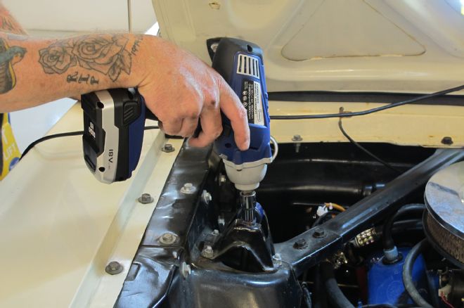
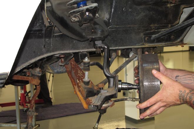
03. Next up, heave ho to the stock shocks. Simply unbolt them from the lower control arm spring perch and from the upper support, shown here.
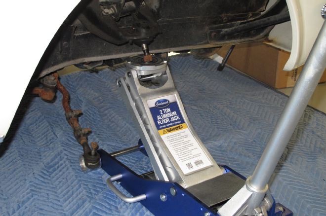
04-05. A coil spring compressor is the safest solution to remove the coil springs, but isn’t always easy to obtain for home shop use (though, most parts stores will rent you one for cheap). The best alternative is supporting the chassis and using a floor jack, as shown here. Jack the control arm up to compress the spring just a little. Remove the upper control arm’s retaining nuts and pry the upper arm out of the shock tower until the arm’s studs are clear, and lower the floor jack to release the spring’s tension in order to remove the spring and upper control arm.
06. The TCP lower control arm and new strut rod are assembled on the hardtop. Leave the strut rod’s Allen bolts loose at this time make strut rod assembly easier. Tighten the lower control arm pivot bolt to 65ft-lb.
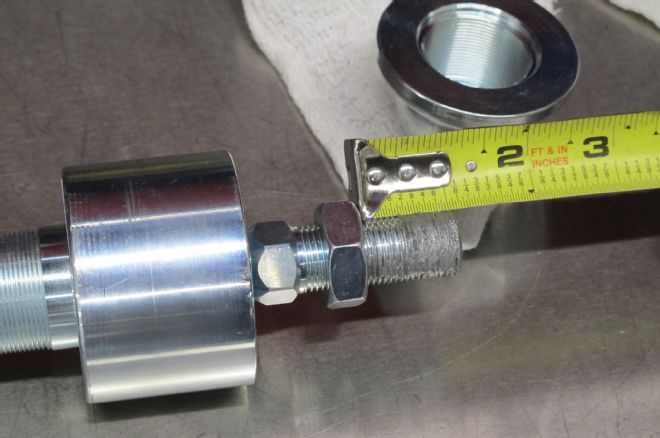
07. Thread the strut rod’s pivot shaft nut on 1 1/16-inch and coat the threads with anti-seize coating. Thread the pivot shaft into the strut rod but do not tighten the jam nut just yet.
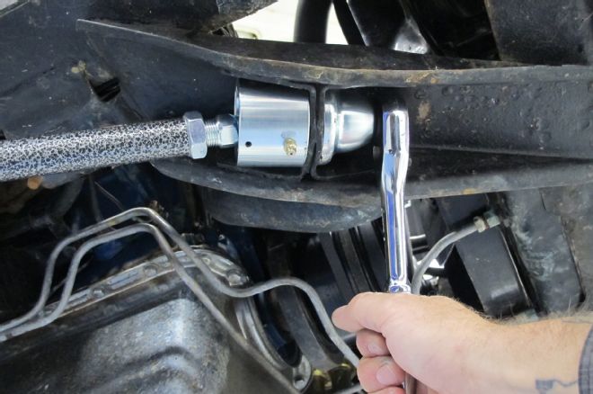
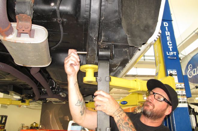
08. Per the included instructions: Chisel out the metal sleeve from the strut rod opening in the frame first, and mount the pivot assembly into the frame, ensuring the grease fitting is pointed down for access. Tighten the large backup nut to 150ft-lb, and finally, install the button-head screw with a dab of thread locker. Adjust the strut rod until the lower control arm is square with the frame and tighten the strut rod’s Allen bolts and jam nut.
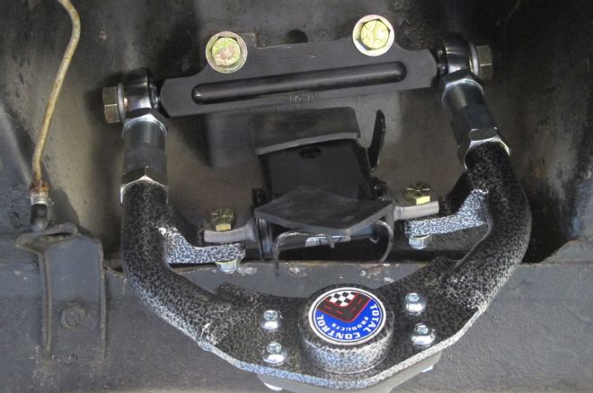
09. Install the new TCP tubular upper arm into the shock tower using the included new fasteners and torque to 95ft-lb. Do not reinstall the old upper-arm alignment shims. The new TCP arms feature threaded adjusters for caster and camber to allow quick and easy adjustment at the arm itself. Ensure the cross shaft is oriented as shown, and the arrow points towards the front of the car. The lowered cross shaft increases camber gain without having to drill additional holes in the shock tower. Note, we’ve also installed the new coil spring saddle on the arm.
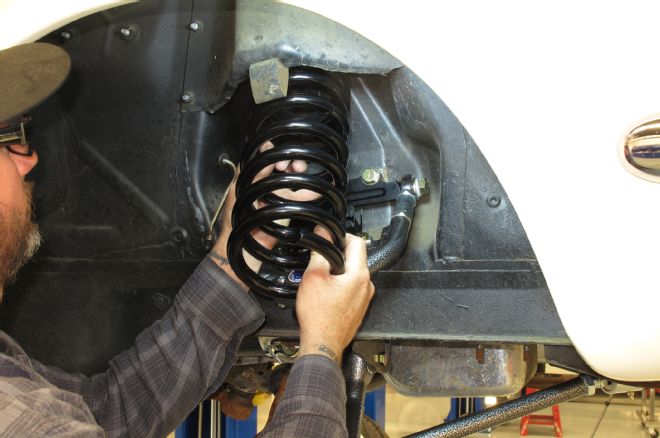
10. The new 1-inch lowering springs are seated into the shock tower’s spring seat (with a new insulator at the top of the spring) and seated into the spring saddle. The upper control arm is carefully raised with the floor jack to seat the spring. Ensure the spring’s tail is properly placed in the saddle at the spring stop tab.
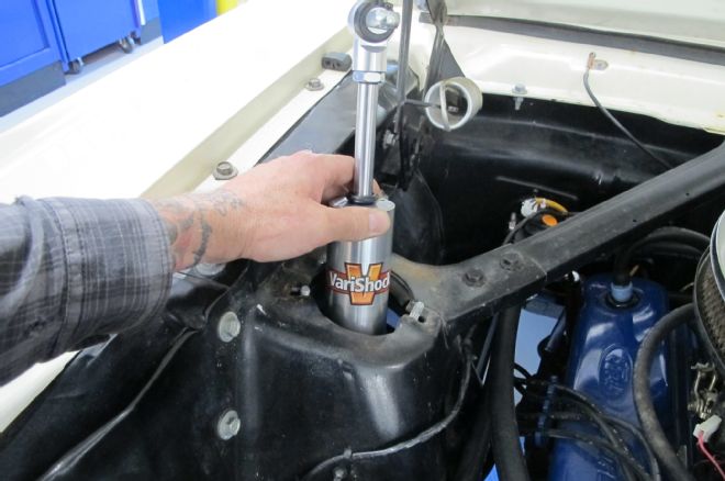
11. For this hardtop suspension upgrade, we opted for the optional VariShock QuickSet 2 double adjustable aluminum shocks. These feature separately adjustable compression and rebound settings—16 adjustments for each, for a total of 256 unique shock valve settings. The shocks bolt in, just like the stock shocks with their own, upgraded hardware.
12. Once the shock is in place, remove the floor jack from the upper arm (as the shock secures the arm, trapping the spring in place). Reinstall the stock spindle using the new castle nuts, lower ball joint spacer, and cotter pins. Tighten the upper nut to 75-80ft-lb, the lower nut to 60ft-lb, and secure with the included cotter pins. Now’s the time to reinstall the tie rod end to the spindle. We ordered TCP’s 1-inch front antisway bar as well, which bolts directly to the stock points on the frame and lower control arms.
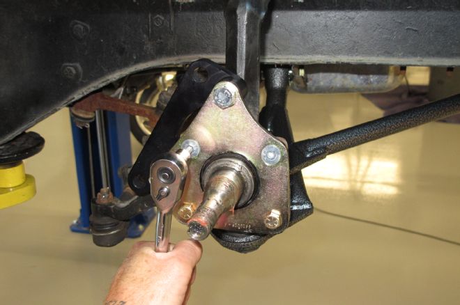
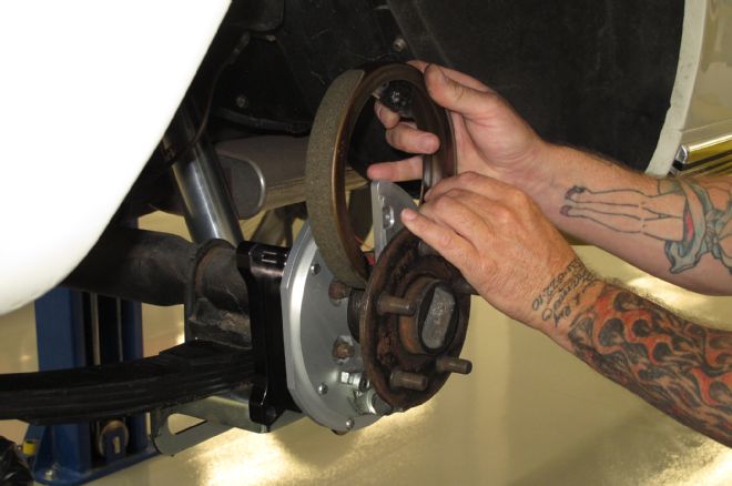
13. For the front brakes, we are installing Master Power Brakes’ Pro Driver Series disc brake conversion for a measureable increase in braking performance. It includes 13-inch rotors along with four-piston billet aluminum calipers. Begin by installing the laser-cut steel bracket to the spindle followed by the CNC-machined billet aluminum bracket using the provided hardware.
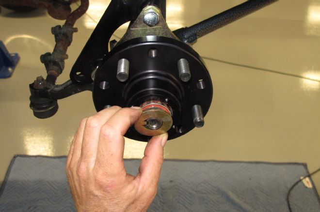
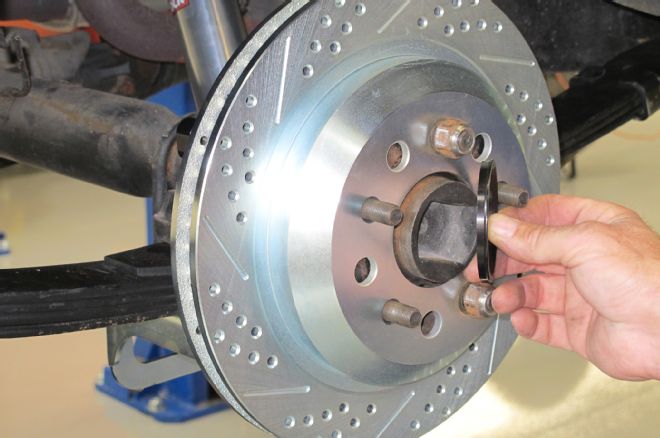
14. Billet aluminum hubs are provided and are a direct fit to the stock Mustang disc brake spindle. The hubs come with the bearings pre-greased and installed in the hubs making installation a breeze. Simply slide the hub into place and seat it onto the spindle per the instructions. Secure the hub with the included washer, castle nut, and cotter pin. The billet aluminum dust cap can be installed next. The hubs come with a dual patter, allowing you to choose between a 5x4 ½ or 5x4 ¾ pattern.
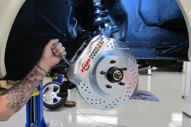
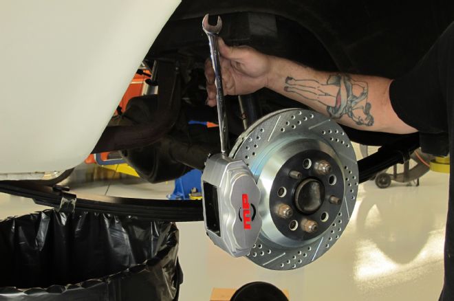
15. The Master Power Brakes system features a 13-inch rotor with directional cooling veins and a cross-drilled and slotted surface. The rotors are zinc-washed for a lifetime of good looks and protection against today’s nasty elements. The four-piston calipers are a USA-made part and are CNC-machined from 6061 billet aluminum followed by a clear powdercoat finish. When installing the calipers, it is necessary to shim the calipers. Follow the instructions to minimize any chance of damage to the system and to keep any annoying brake noise from happening. Remember, 17-inch wheels are required for the Pro Driver Series brakes. Templates are available from Master Power to guarantee fitment before pulling the trigger on an expensive set of wheels. Attach the brake hoses and get ready to bleed once the rest of the system is complete.
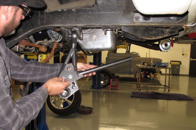
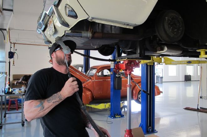
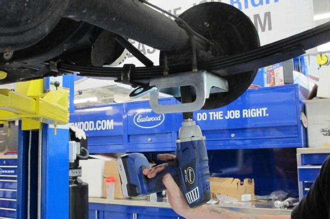
16. Moving to the rear of our hardtop, we start with the removal of the leaf spring plates. We’re supporting the rear axle with a jack and fixture, but at home you can simply use two jack stands on the axle tubes. Once you free up the leaf spring plates and U-bolts, you can access the top of the shocks inside the car and remove the old shocks.
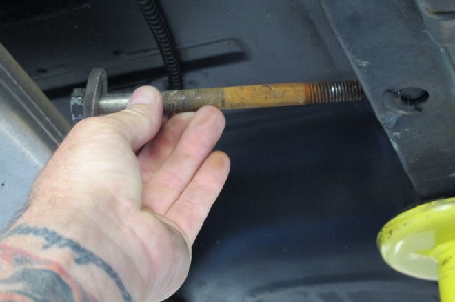
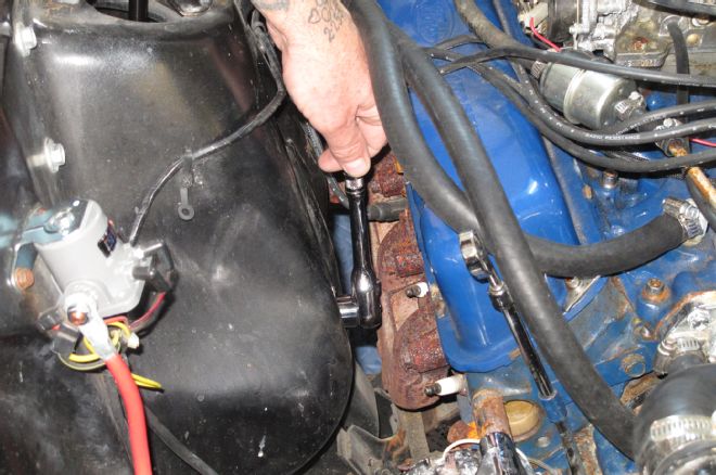
17. Remove the front spring eye-retaining bolt next. This bolt may be seized to the bushing, depending upon how old your suspension is. Often, we’ve had to cut this bolt free with a reciprocating saw, but we got lucky and our bolts came out with a little elbow grease. Some aftermarket exhaust systems may need to be temporarily loosened to allow access to the bolt’s nut on the inboard side of the frame rail.
18. With the front eyebolt removed, the leaf spring can swing down out of the way. Remove the upper shackle retaining nut and pull the spring and shackle assembly free.
19. Don’t worry if you had to cut your front eye bolt to remove your old leafs, as the TCP leaf springs include urethane, front eye bushings with all new hardware. Install the spring into the frame pocket and loosely install the eyebolt at this time.
20. At the rear, clean the frame rail openings of any debris and old bushing and install the new urethane shackle bushings with the included lube. Assemble the rest of the shackle, as shown. Install the remaining bushings in the rear mid-eye leaf openings and loosely bolt the leaf spring to the shackle.
21. Install the new leaf spring plates using your original U-bolts. TCP does offer a larger diameter heavy-duty U-bolt kit for 3-inch axle tubes under PN LSP-03 if your U-bolts have seen better days. Once the leaf spring plates are secured, tighten the front and rear leaf spring hardware.
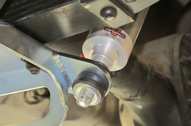
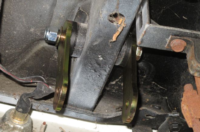
22. The VariShock QuickSet 2 double adjustable shocks bolt into the stock upper mounting location and to the new leaf spring plates using their included hardware. Over-tightening the mounts causes the bushings to deform and split in short order. You want just a bit of light deflection in the bushing body when tightened properly, as seen here.
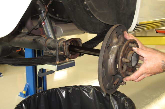
23. With the suspension upgrades finished up and the front brakes installed, all that is left is to upgrade the rear brakes and install a new master cylinder. To install the rear brakes, begin by removing the axles along with the stock drum brake backing plates. The factory bearing retainer plate is not required with the new system so we recommend removing it completely. In addition, per the instructions, the outer axle flange can be no larger than 5.900-inches in diameter. If your axle flanges are larger, have a machine shop with a lathe turn them to the proper specs. Once everything is removed, the axles can be slid back into place. Remember to check your axle bearings at this point and replace them if necessary.
24. For the rear brakes, we are installing the same Pro Driver Series kit from Master Power. The rear utilizes a 12-inch rotor and a slightly smaller four-piston billet aluminum caliper. Together, these two systems should provide a well-balanced brake system. To begin the rear installation, slide the billet aluminum backing plate up from the bottom and attach it to the axle housing using the factory T-bolts and nuts. This new backing plate doubles as the bearing retainer.
25. The rear system features an internal parking brake assembly. This is very similar to what the OEs do and provides an efficient park brake system once the rotor is installed. The one-piece park brake shoe drops into place and seats into the park brake actuator at the bottom, and is secured at the top by the shoe retainer bracket.
26. The rear rotors are a 12-inch version of the front rotors, with directional veins for proper cooling and the same slotted and drilled surface and zinc coating. The rear rotors must fit in a hub-centric manner. Included in the system is a pair of centering rings, if your axle centers are smaller than the center of the rotors.
27. Just like the fronts, the rear calipers must be centered over the rotors and shimmed if necessary. Follow the provided instructions for proper shim location. Once the shims are in place, place the caliper over the rotor with the pads installed and tighten all fasteners to the recommended torque specs in the instructions. Install the provided brake hoses to the rear axle along with the park brake cables.
28. Although the front brake hoses connect directly to the factory hard lines, at the rear the new Master Power calipers use a braided AN hose with banjo fitting at the caliper end. Brackets and clamps are included to secure the hoses to the axle tubes. You’ll have to bend up new hard lines between the axle’s Y-block and the calipers, as we did here.
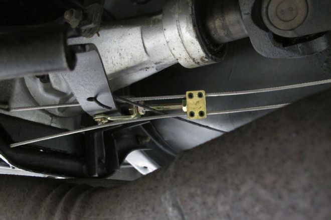
29. The new internal parking brake mechanism is connected to the original parking brake lever under the car using new cables and this adjustable cable block. Feed the cables through the block and adjust the assembly for proper parking brake application. Tighten the Allen set screws and cut off the excess cable length.
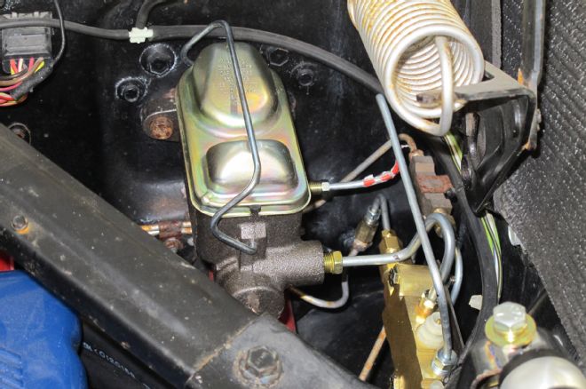
30. To wrap the disc brake upgrade, we improved the hardtop’s safety a bit with a dual bowl master cylinder and disc/disc combination valve to split the brake system into two separate circuits like a modern brake system. You’ll have to fabricate a few small hard lines and give them double-flare ends, but it’s nothing you can’t accomplish in your home garage.
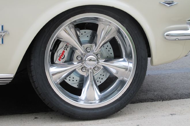
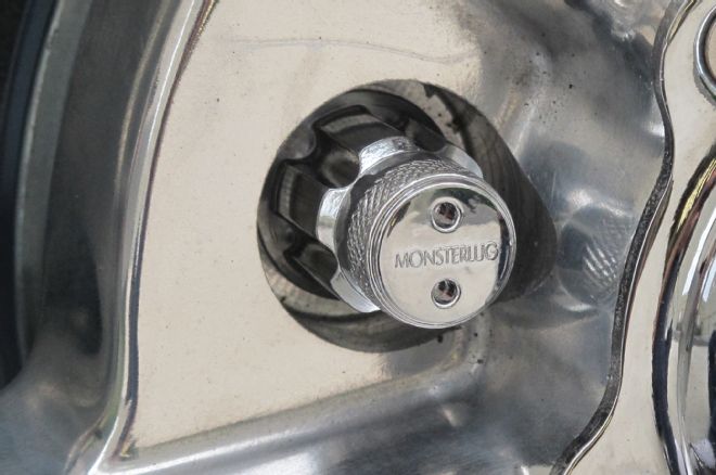
31-32. To put the hardtop back on the ground, we ordered a set of 18-inch Showwheels Streeter polished, five spokes, wrapped them in Falken Azenis FK453 rubber, and bolted them on with a set of Monster Lug spline-drive lug nuts from Mackin Industries. The Falkens are sized at P215/45ZR18 on an 18x8 wheel up front and P235/40ZR18 on an 18x9 wheel out back.