Power steering, standard equipment on virtually every vehicle today, was also a very popular option back in the day, produced by the millions. Those systems have an outstanding service life. Other stuff goes down—engines spin bearings, transmissions cook their clutches and bands, and sheetmetal gets tin worms—but even with an old dusty derelict Pontiac drug out of a barn, the power-steering system is probably still functional, even if leaky.
There comes a day when the worn-out steering box has dumped its last load-bearing bits, shaft shavings, and funky flakes into your delicate drops of Dexron. Even if the ancient pump is still pumping, if you're restoring a Poncho, the pump has to be part of the restoration, right? You're not going to reinstall the old chipped, grease-ball pump on your fresh engine, are you?
So then, whether your motivation is function or cosmetic or possibly both, when the need to rebuild hits, here's how it's done.
It's not terribly difficult, but there are a few steps that have to be done just right—like getting the pump vanes installed facing the right way, or your pump will not work right. One guy who knows how to do it right is Chip Woyner of Power Steering Services in Reeds Spring, Missouri. He's been rebuilding power-steering systems full time for almost 20 years, and that's long enough to him to know them like the back of his hand.
One thing that Chip stresses is to rebuild the whole system at one time—do the steering box and the power-steering pump together so that you don't contaminate one freshly rebuilt component with the dirty fluid from the other.
These are reservoir-type pumps, where the sheetmetal housing forms the reservoir for the fluid. Style details can vary, but the function is the same.
There are cheaper rebuilds available, but Chip's power-steering boxes are carefully and completely remanufactured (prices start at $169), and if you rebuild the pump and steering box together, you'll never have to worry about them again. "I guarantee that my pump will work with my gearboxes for life, and if you ever have a problem, I'll take care of it," Chip says.
You can't beat that, can you?
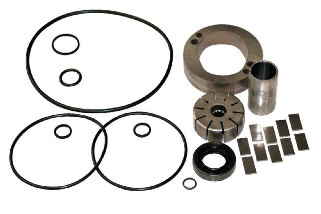 1. Every power-steering pump rebuilt by Power Steering Services gets all new parts and seals. That’s why it can carry a lifetime warranty. Vanes, cam, bushings, and seals are all replaced.
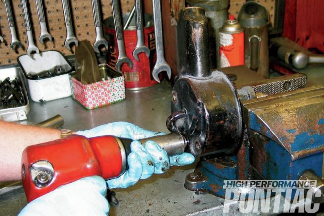 2. With goggles or safety glasses on, disassembly begins by removing the pulley on the front with a power-steering-pulley puller (for pressed-on pulleys). A regular gear puller that grabs the outside of the pulley will ruin the pulley. The puller must act on the pulley’s hub. If a nut retains the pulley, remove the nut, support the pulley’s hub from behind, then tap squarely on the shaft’s center with a soft mallet. Threading the nut to where it is flush with the edge of the shaft will also prevent the threads from being damaged. With the pulley off, the keyway is removed from the front shaft. These parts will be reused, so set them aside. Moving around to the back, remove the two studs/bolts (some pumps have only one), and the pressure-hose fitting.
 3. On the pressure-hose fitting is an O-ring. It needs to come off and a pick works nicely.
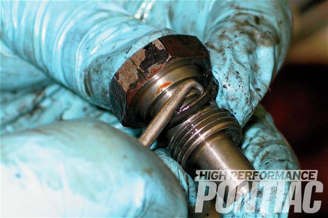
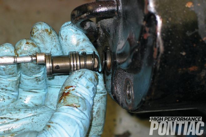 4. Inside the opening where you just removed the pressure-hose fitting is the pressure-flow valve and spring. They need to come out, too, and a magnet wand pulls them right out.
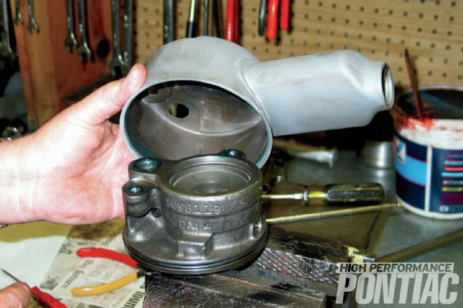
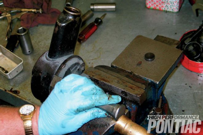 5. Now the sheet-metal reservoir is removed by tapping on the edge with a blunt driver. Work around the circle and don’t get in a hurry. Lots of lighter taps are much better than a few he-man blows. Too much force can distort the sealing surface, and that’s bad.
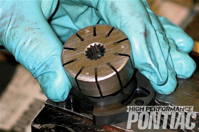
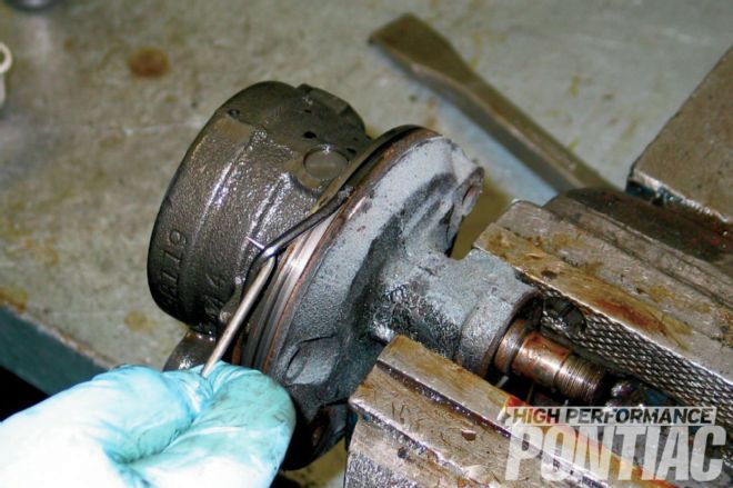 6. With the reservoir removed, the pump is exposed. Around the edge is a big O-ring that seals the reservoir. Remove it. On the back of the pump, remove the O-rings from the holes where the bolts and pressure fitting went.
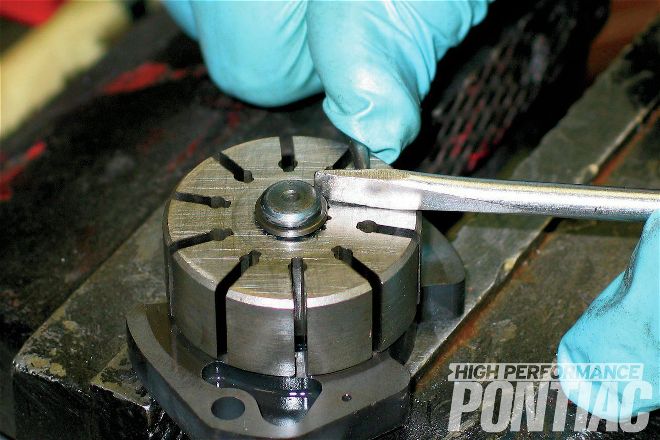
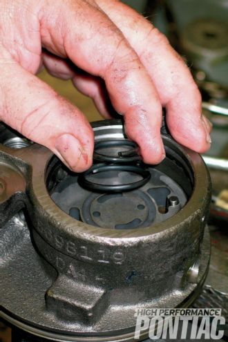
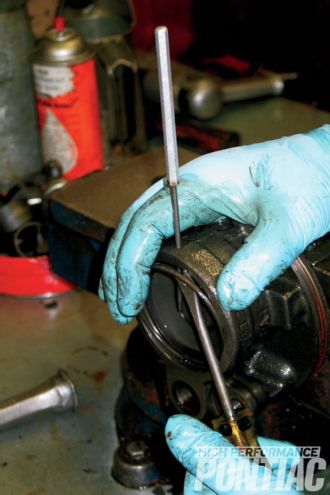 7. Now it is time to get into the pump’s internals, which are held in place by a snap ring. A punch inserted through the release hole on top will lift the ring out of its groove so you can pry it out. Take care that it doesn’t go flying. It’s also a good idea to hold a rag over the hole, as when the snap ring releases there is some spring pressure beneath the end cap.
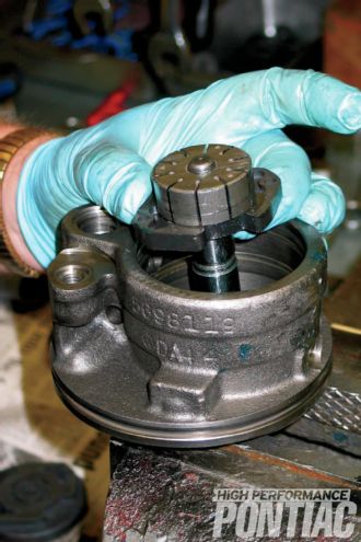
 8. With soft driver and mallet, gently tap on the front of the shaft and get ready to catch parts as they come out the back. In order, they are: end cover, pressure spring, pressure plate, cam ring, two guide pins, and vanes. The rotor and thrust plate will come out as an assembly. There are two O-rings in there that also have to come out. Next, pull the seal out with a puller, then with a hammer and driver, drive the bushing out from the back of the pump.
 9. There is one more step in disassembly. With the rotor and thrust-plate assembly in a vise, remove the snap ring holding the rotor onto the shaft. It’s a stout ring, and will probably take some careful effort.
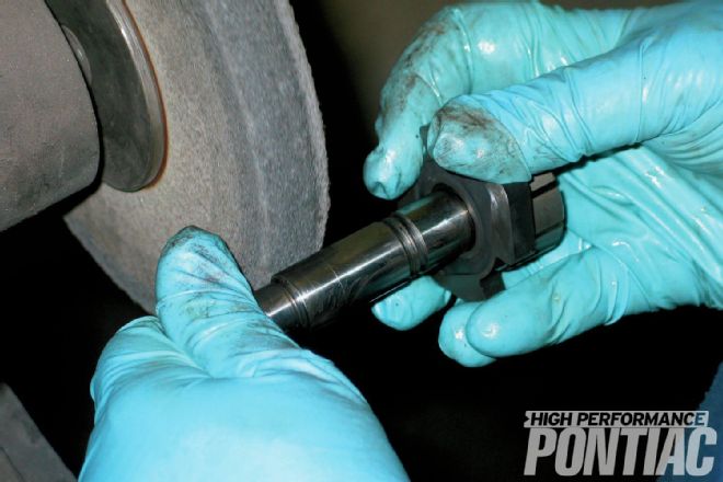 10. Cleanup starts with a hot detergent bath for parts that will be reused, and then it is into the solvent-parts washer. The next stop is the wire wheel where particular attention is paid to the sealing surfaces. Only the reservoir then goes into the bead blaster, and the machined shaft gets a light cleanup on the cloth wheel. Heavy corrosion here calls for replacement from a donor pump, which Power Steering Services stocks plenty of.
 11. A new bushing is pressed into the pump’s shaft bore. Once it is completely seated, a new seal is also pressed into place.
12. The rotor is replaced with a new one from the kit. It is splined to the shaft and held in place with the stout snap ring shown in Caption No. 9. Take extra care when handling this snap ring—they love to fly off into the darkest corners of the shop. Once in place, Chip makes sure it’s seated with a firm squeeze from a large pair of pliers.
11. A new bushing is pressed into the pump’s shaft bore. Once it is completely seated, a new seal is also pressed into place.
12. The rotor is replaced with a new one from the kit. It is splined to the shaft and held in place with the stout snap ring shown in Caption No. 9. Take extra care when handling this snap ring—they love to fly off into the darkest corners of the shop. Once in place, Chip makes sure it’s seated with a firm squeeze from a large pair of pliers.
 13. Two new O-rings are installed in the large round bore in the back of the pump case where the pump internals are about to be installed. Now the rotor shaft is lubed with hydraulic fluid, then the rotor/shaft/thrust-plate assembly is dropped into place.
 14. Next, install the two guide pins into their holes. They align the rest of the pump components during reassembly.
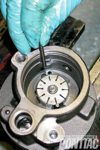
 15. Slide the vanes into the slots on the rotor. There is no top or bottom, but they have to move freely. One of ours didn’t and had to be lightly de-burred on a piece of fine-grit emery cloth. If you’re reusing a rotor and vanes, the rounded edge of the vane goes outward towards the cam-ring surface. With all the vanes in place and moving freely, slide the cam ring over the guide pins and around the rotor, taking care not to scratch its polished surfaces. It has to be oriented correctly. One of the small holes in the ring is slightly elongated. Place this elongated hole face down on the dowel pin farthest from the pressure port. This is the only way the pump will function correctly. It is not dummy-proof—it can be installed wrong, in which case you’ll have no pump pressure. Once everything is installed, make sure it turns freely, and that the vanes move freely.
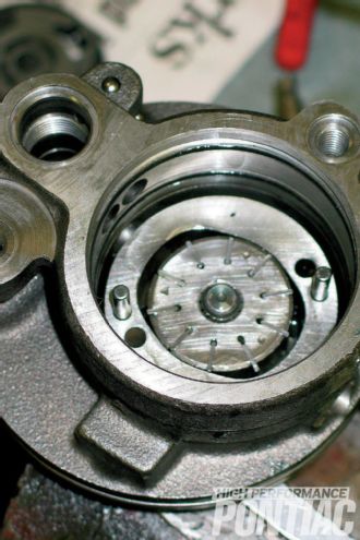
 16. Lubricate the rotor and vanes with a few good squirts of power-steering fluid because they’re about to get covered up. The machined surface on the pressure plate is lapped with a few strokes across the emery cloth, and then installed in the pump case. Heavier wear from running dry or from high miles requires replacement.
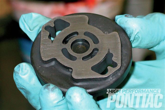
 17. The big spring goes in next, and sits in the groove cut for it. The side with the spring groove goes toward the back of the pump.
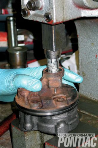
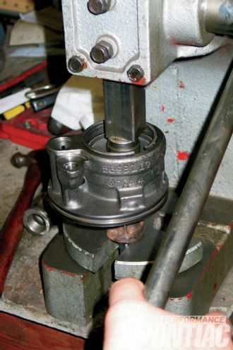 18. Install the end cover and compress it in a press. With the end cover compressed, install the snap ring and make sure it is fully seated before releasing the press.
 19. Four rubber O-rings go on in preparation of installing the reservoir: The big one around the edge of the pump case, the next largest goes in the discharge opening, and the other two go in the holes where the studs/bolts go. The O-ring groove gets a dab of grease, as does the flange on the pump case, once the O-ring is in place. Next, the spring for the pressure-flow valve is greased and installed, followed by the pressure-flow valve. The screen side of the valve goes towards the front of the pump.
 20. Lightly grease the areas of the reservoir that contact the O-rings. With the reservoir on, but not tight, the pump is flipped over in the vice and the O-rings are checked to make sure they’re centered. Once any adjustments are made, the reservoir is fully seated with a clean rubber mallet, and then the two studs/bolts (one for Pontiac) are installed.
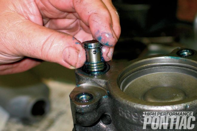
 21. The pressure-hose fitting gets a new O-ring too, but be sure that the O-ring goes in the groove nearest the nut. If it accidentally goes in the adjacent groove with the hole, you won’t have the proper pressure and the pump will not function right. With the O-ring in the right groove, apply a little grease to seal it, then install it and tighten it with a 1-inch socket. The keyway is then tapped into the front of the shaft.
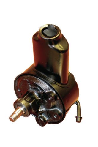 22. The finished pump is prepped and painted with either enamel as standard finish, or with lacquer for extreme detailing. If the customer sends the pulley with the pump, the pulley will also be refinished at no extra charge. Brackets are extra.