Everybody knows that brakes can be the most important aspect of your car’s makeup. After all, what good is going fast if you can’t stop the car? You need brakes to race. It’s that simple. Otherwise, the only stopping you’re likely to be doing involves a concrete retaining wall, lots of noise and the potential for serious injury.
When it comes time to put new brakes on your racer, don’t scrimp on parts or installation. Your brakes are sometimes the only things between you and a sudden stop against something hard and painful.If you have any doubts about your welding and fabrication ability, it is best to have a professional install the brake system.
For the purposes of this story, we have decided to install a set of new brakes on a race car from stem to stern. For this, we went with a four-piston Wilwood system and a Dan Press Industries recirculating kit. For the test car, we chose the NASCAR Goody’s Dash machine fielded by Crenshaw Motorsports. Crew chief Bruce Jones did the installation, so follow along and see how it’s done.
Jones started with the Wilwood master cylinders in the front of the car and worked his way to the rear. There are three master cylinders: a one-inch bore for the front brakes, a 17/8-inch bore for the rear brakes and a three-quarter-inch bore for the clutch. Normally you would have to drill holes for both the master cylinder body and mounting bolts, but since this car had a brake system in it before it was refurbished, the holes were already in place.
Jones simply attached the master cylinders and bolted them down. Because a DPI Sure Stop 2 Master Cylinder Equalizer and Brake Fluid Recirculator kit were installed, a little work needed to be performed prior to the installation of the brake reservoir tanks. A hole was drilled into the front of each reservoir, fittings were screwed in and a plastic tube was attached to connect the two reservoirs together. As the brakes are applied, the DPI recirculator moves the brake fluid around the entire system to prevent it from overheating. When the pedal is released, the fluid is returned to the reservoir, but with the DPI kit installed the majority of the fluid goes into one reservoir. This balancing tube lets the fluid drain from reservoir to reservoir preventing either side from going empty.
With the master cylinders in place on the firewall, Jones attached the DPI kit. This kit is designed to screw onto the front of each master cylinder where the normal brake line would exit. From these blocks, the brake lines are connected and run to the calipers. A second set of brake lines is used as return lines in the front of the race car. This set of lines is attached to the caliper via the bleed hole.
If you are using two-, four- or six- piston calipers, a crossover tube needs to be added at the bleeders and the return line gets attached to one of the feed holes.
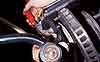
Next, Jones needed to attach mounting brackets to the front spindles. To make sure that the bracket is properly aligned so the Superlite 111/ST caliper is parallel to the HD 48-vane directional rotors, Jones attached the caliper to the rotor and bolted the bracket onto the caliper. He then attached the rotor onto the spindle. The bracket was moved into the proper position and tack-welded in place. Jones removed the caliper, rotor and spindle to fully weld the bracket in position.
The bracket must be mounted so the rotor and caliper are parallel. With the bracket secure, Jones remounted the front assembly and moved to the rear. The rear axles had the wrong mounting brackets so Jones continued by removing the rear axles, which needed to be done to change out the rotors anyway. He cut the old mounting brackets off with a torch. Jones used an angle grinder to clean off any residue left from the old bracket and continued the line-up process as he did in the front. The only difference was that the rear mounting brackets wrapped around the axle tube in two pieces and bolted together in clamp-like fashion. The bracket was spot-welded onto the axle tubes to prevent it from sliding around from the braking force. Once again, the rear brake assembly was reinstalled and bolted to the new mounting bracket.
Moving on, Jones installed the remainder of the brake lines. He used three- sixteenths-inch bulk brake line, bending it to fit the car as if you could buy custom factory lines and three-sixteenths-inch braided whips to attach to the calipers.
With the major brake components installed, the time had come to add a way to use them. Jones installed the forward-swing mount brake and clutch pedals and remote brake-bias adjuster cable. The pedals were mounted in freshly drilled mounting holes on the back side of the firewall adjacent to the master cylinders. The brake bias adjuster was mounted on the driveshaft hump in reach of the driver and to the backside of the brake pedal’s control balance bar. This bar slides from side to side to change the amount of pressure applied to the front and rear master cylinders.