Internal combustion engines are fairly simply machines. When you break it down, they are nothing more than air pumps. When it comes to making horsepower and torque, the simple fact is the more air you can get in and out, the more potential there is for horsepower. As you start to examine each component and its function, the simplicity of it all seems to vanish. The basics end up not being so basic, and to a novice enthusiast, there can seem to be a bit of black magic at play.
When you dissect the operation of an engine, air and fuel need to enter the engine, be compressed, ignited, then exhaust gasses expelled. As simple as this sound, each component and their individual functions can become quite complex. For this story, we chose intake manifolds to examine under the microscope and talked with some industry experts about their designs, and the role they play in every engine.
Whether that engine is a low-emissions hybrid or a 980ci Pro Mod mountain motor, the intake manifold plays the same role—get air and fuel into the cylinder heads, and ultimately, the combustion chamber. While this may seem like an obvious fact, there is a lot that goes into it. The basic design of most intake manifolds (carbureted or fuel injected) consists of an inlet, a plenum, and runners. Again simple, but each piece plays a key role in the amount of horsepower and torque the engine can make, as well as at what point in the rpm band.
An engine is a puzzle, and while each piece needs to fit together to achieve high levels of efficiency, we are only looking at one piece. We’ve established that the purpose of the intake manifold is to introduce air and fuel to the combustion chambers. In a carbureted application, fuel is combined with air as it passes through the carb. From there, the fuel atomizes inside the plenum and is pulled into the combustion chamber through the runners by the engine’s vacuum. In an EFI combination, the fuel is either introduced in the throttle body, similar to a carbureted setup, or in the intake runner in the case of port injection. This requires intake manifolds with vastly different designs when you look at inlets, plenums, and runners. Each of these parts also has a direct affect on not only power and torque, but where the engine produces it.
Runner length is one such variable that has a direct relationship on where that power is produced. This is due to volume and air speed, but also the pressure waves that pass through the intake runners in both directions.
“The intake manifold, although not a moving part, has fuel and air travelling through it at peak speeds of up to 550 feet per second (ft/s) so it can have a great influence on torque and horsepower,” explains Brent McCarthy, Chief Engineer at Edelbrock Performance. “The manifold generally has a single entry point, either a carburetor or a throttle body, and must distribute from there to eight different cylinders. The source of energy to move the air comes from both the slight bit of exhaust scavenge during valve overlap and the downward motion of the piston. So really, the vacuum pulling in the air and fuel mix is anything but constant. This lack of consistency sets up pressure waves, which with a good design can be used to greatly enhance torque, or with a bad design can really screw things up.”
These pressure waves have a direct affect on horsepower and torque. The design of the intake manifold plays a large part but many other things in the overall system also affect the waves.
McCarthy continues, “There are pressure waves which travel up the runner and are reflected back when they hit the plenum. The frequency of the acoustically generated waves is influenced by rpm, cylinder volume, the pipe length and diameter, and the plenum volume. The frequency of pressure waves created by valve action depend on valve speed and cam profile. In either case, the waves travel at the speed of sound. Since it takes longer for a wave to travel up and back on a long runner, it works better with low frequency waves (lower rpm) and short runners match up with higher rpm. Long runner manifolds, like the old TPIs (approx. 19 inches) end up with a really tall and narrow torque curve. Short runners, like the LT1/LT4 from the ’90s have a broad flat torque curve, but are missing the peak. On carbureted manifolds, dual-planes have slightly longer runners than single-planes, helping mid-range torque.”
Beyond the separate components that make up an intake manifold, there are design features that greatly impact power and the “personality” of the engine. While runner length is a big part, the cross-sectional area and tapper of the runner is equally important. As the runner tapers, air speed within the runner increases. The cross-sectional area is the area of the runner perpendicular to the flow path of the air. A larger area will equal slower air speed, while a smaller area will equal higher air speed. All engines have an optimal air speed for peak efficiency, and, according to Edelbrock, that speed is generally 350-400 ft/s peak velocity at peak torque.
“The most important factor when it comes to intake manifold design is fully understanding the application and intended use,” explains Tim Torrecarion, Director of Marketing and Sales at Air Flow Research. “This is the reason why we see various intake designs from a single-plane to dual-plane to variable runners. By controlling the volume and velocity of the incoming air charge, you are able to influence different characteristics on how the engine will generate power (i.e., responsiveness, powerband, etc). Longer runners equal better low-end power. Shorter runners equal better top-end power. Examples of these are the variable intake tract designs from the OEMs. If you look at it from the aspect of quantity of air molecules, more volume means more air; and different engines/applications will require different designs; which is why racers will play with carb spacers.”
Because no two engines are the same, the manufacturers have an extremely challenging design process whenever a new intake manifold is developed. Brent McCarthy sheds some light on this process.
“Runner length, runner area, taper rate, entry shape, throttle body or carburetor location, and size are all important. We design manifolds using 3D CAD software so we can move a wall over 0.010-inch and see how the move affects the other runners and the plenum shape. It takes lots of time and experience to optimize the design. A good test program will include making a variety of standard changes, evaluating the results, and then trying new specific ideas. The flow bench is a good way to check for flow capability and flow field shape and speeds. However, you can have a great flowing manifold on a flow bench, and if it doesn’t have the right runner length or port entries to take advantage of dynamics, it’s not going to run very well on an engine.
Intake manifolds can be extremely complicated when you dissect each part of the design. Small changes can make huge differences in the overall package. Next month we will continue our look at intake manifolds and get into specific styles and designs and help you narrow down exactly what you need for your classic or late-model hot rod.
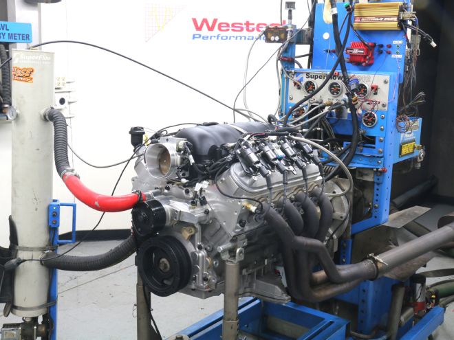
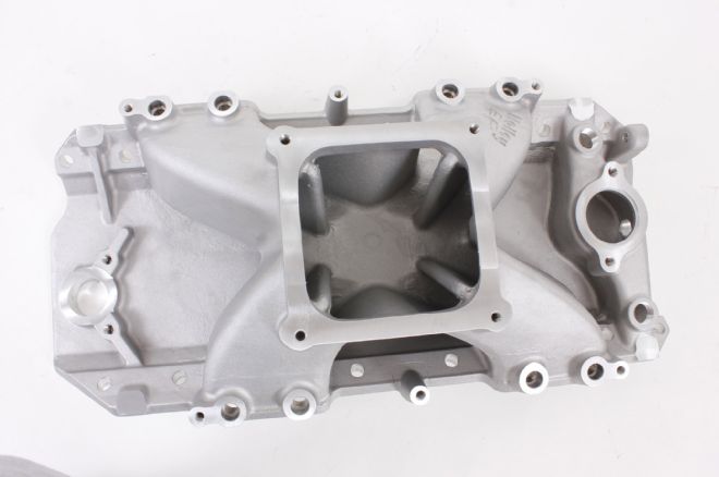 Holley Performance Products recently released this single-plane, 4500-flange, EFI intake manifold (PN 300-564) designed for large-cubic-inch big-block Chevy applications. The large plenum feeds air and fuel to the short intake runners that guide the air/fuel mixture to the cylinder heads.
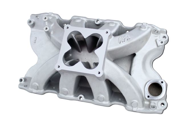
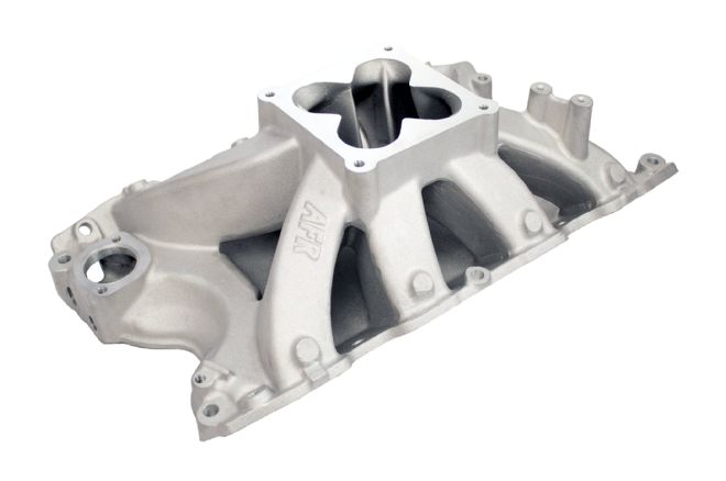 This single-plane intake manifold from Air Flow Research is designed for carbureted applications, but like many intakes can be modified for EFI or nitrous applications. The plenum and runner design is similar to other single-plane manifolds, but the changes come when you look at the volume and shape of the plenum and runners.
 The intake manifold’s design dictates a lot of the engine’s horsepower and torque characteristics. The size of the plenum, as well as length and shape of the runners play a part in the engine’s powerband. The tapper of the runners changes the velocity of the air in the runners, which is directly related to the engine’s efficiency.
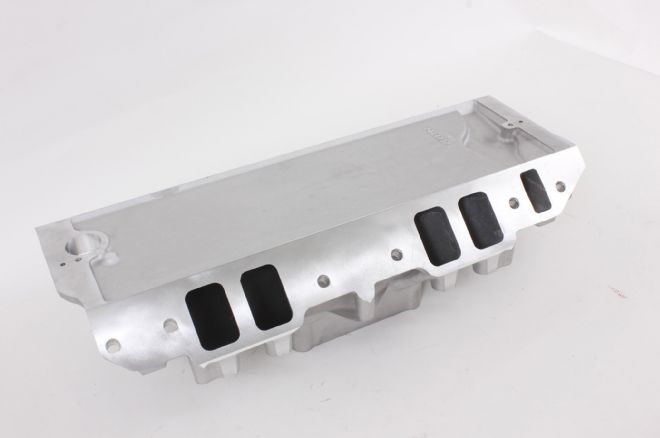 As the intake runners tapper in size, the velocity of the air/fuel mixture speeds up. According to Brent McCarthy at Edelbrock, all engines have an optimal air speed for peak efficiency, and that speed is generally 350-400 ft/s at peak torque.
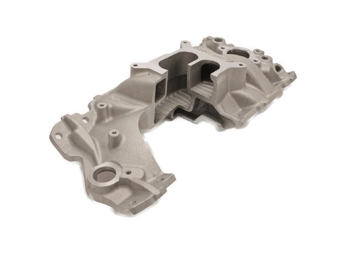
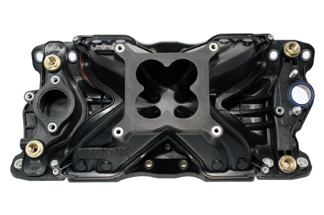
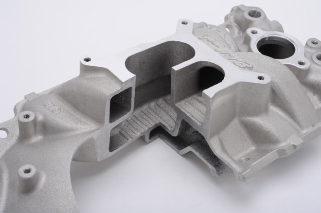 The cutaway of this Edelbrock dual-plane intake manifold shows the difference in design over a single-plane. Generally, a dual-plane intake manifold will make more torque than a single-plane, but a single-plane will produce more horsepower at higher engine speeds.
 The Edelbrock dual-plane manifold has two plenum areas that feed the runners. This design usually has a smaller plenum with longer runners that increase torque.
 Air Flow Research also makes intake manifolds out of materials other than iron or aluminum. This composite design is significantly lighter than cast aluminum, and according to AFR, has none of the heat-soak issues commonly associated with aluminum intake manifolds.
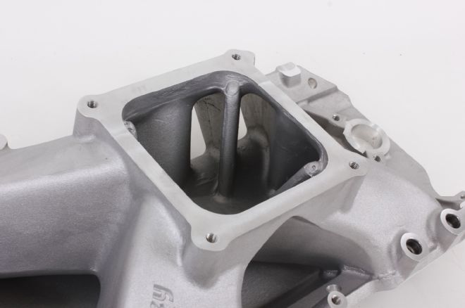
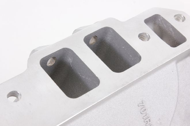
 When you look at the plenum in this single-plane intake manifold from Air Flow Research, you can see the dividers leading to the opening of the runners. These help with air and fuel distribution. They are also common areas where porting can help increase power.
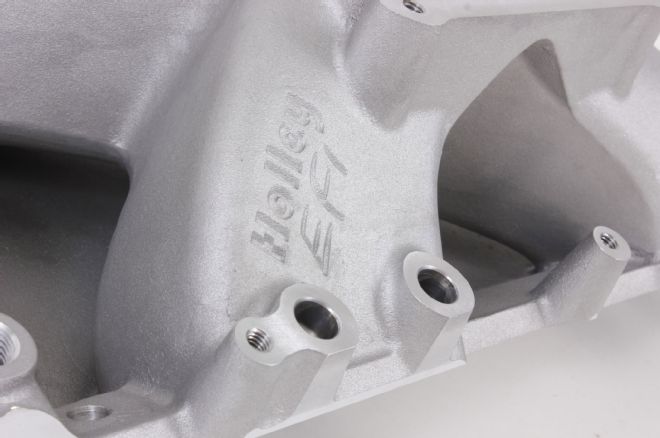 In a carbureted application, air and fuel are combined in the carburetor and introduced to the engine through the intake manifold. In Holley’s EFI intake, an injector in each intake runner introduces fuel into the engine as the air charge enters the cylinder heads. The significantly higher fuel pressure gives better fuel atomization.
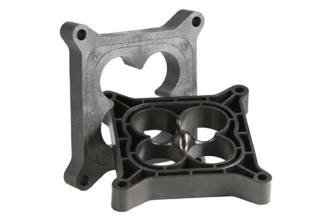 Carb spacers are a great way to tune the characteristics of the engine. This is because the spacer changes the volume of the plenum. These spacers from Air Flow Research show a couple of different designs. One is a four-bore spacer and one is an open design. The open spacer increases the volume of the plenum, which can change the torque curve. The four-bore design can have different tappers, which will change air speed entering the intake manifold, which will also affect horsepower and torque.