In this second installment of the Great American Engine Build, we will be assembling all of the parts to get ready for running the engine on the dyno. If you remember, as we stated in part one, this is a street stock motor that fits the rules of Circle Track’s Great American Racing Series and as such, may, or may not, be legal for your particular track or series.
The purpose of this build is to highlight the various phases of an engine build. We have presented quite a few engine builds over the past few years and one of the reasons we think it important to do these seemingly identical builds is in the use of different engine builders.
We find that each builder has techniques and routines a little different than the others, much the same as setup guys or tire specialists. By following the build of each engine constructor, we draw out the specialized methodology each one has developed over many years of work in this area.
For those of you who are interested in building your own motors, or are interested in how your engine builder puts your motor together, these articles will give you a lot of insight on not only how it is done, but the extra care that goes into each part of the build and the special secrets the builders have incorporated to end up with a product that will perform well and survive the punishment of racing.
As in the last installment, our expert engine builder is Mike Hupertz with ISON Racing Engines out of Concord, OH. He will be narrating the photo captions that will explain each part of the build. As in Part one, read carefully to learn his unique methods as we do the final assembly work.
As a reminder and lead-in to this segment, in part one of the G.A.R.S. engine build, we prepped the block by de-burring all of the sharp edges, milled the deck to the correct height, bored the cylinders to near the correct size, finished honed the bores to final sizes, balanced the crank, checked the bearings for size and fit in the block, pistons and rods, gapped the rings, installed the cam and set the cam timing.
Now with all of that done, we are ready to complete the assembly of the block and finish it out to make ready for a run on the shop dyno to ensure that everything works as expected and that our power numbers are what we should see for this motor combination.
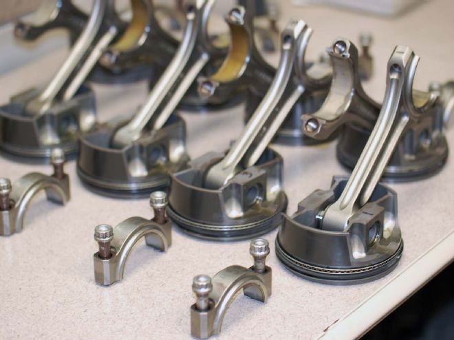
 In preparation for final assembly, now that we have prepped the block, installed the cam, and degreed it to the proper centerline using the number one piston. We lay out the remaining pistons. The rods have been installed and the cylinder number etched on them, so we know which cylinder they will occupy.
The rod and piston combinations, including rings and bearings, have been statically weight matched to within 1 gram. We then made our bob weights up and dynamically balanced the crank seen in the previous article. Vibrations in a high-rpm motor are bearing killers.
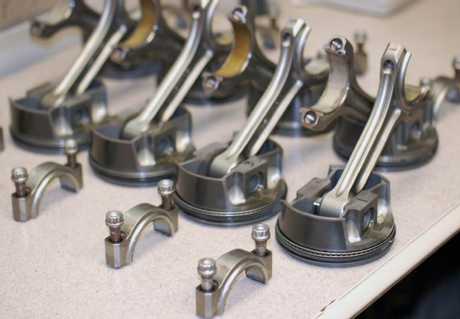
In preparation for final assembly, now that we have prepped the block, installed the cam, and degreed it to the proper centerline using the number one piston. We lay out the remaining pistons. The rods have been installed and the cylinder number etched on them, so we know which cylinder they will occupy.
The rod and piston combinations, including rings and bearings, have been statically weight matched to within 1 gram. We then made our bob weights up and dynamically balanced the crank seen in the previous article. Vibrations in a high-rpm motor are bearing killers.
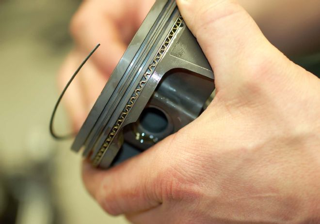 We now install the piston rings carefully. Some engine builders will clock the ring gaps differently than others. For typical V-8 applications we install the oil expander first (corrugated ring) facing the gap toward the intake valley followed by the support rails top and bottom of the expander, we shift them off the centerline of the expander 30 degrees or so with one to the left and the other to the right, we then install the second and top ring, ensuring the dots are up, positioning the gaps 180 degrees from each other, parallel to the wristpin.
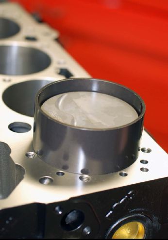 We first lubricate the bores well and when we insert the piston into the cylinders, we use a tapered ring compressor; the tool is a tapered sleeve that has been hard anodized so the rings will not hang up as the piston is inserted into the bore and provides a very smooth transition for the rings. With the rings today getting thinner and thinner this is a must-have tool. Once the piston is in the bore, remove the compressor and ease the piston down, paying very close attention that you do not hit the counterweight of the crank or nick the journal as you’re matting the two together.
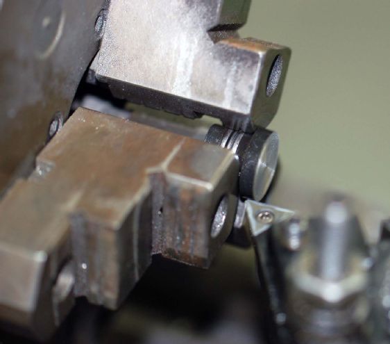 Before we could put the oil pan on we had to establish the camshaft endplay, for this build we needed to put the cam button in the lathe and face some material off. A couple testfits later we arrived at our 0.006 endplay dimension. We can now install the cam cover and get ready to size and install the damper.
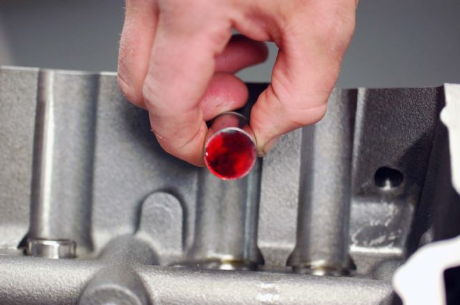
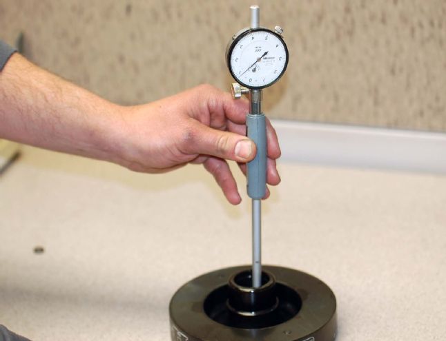 First, we check the bore size of our damper. We want to provide a tight fit, but not so tight that the damper will be hard to remove later on.
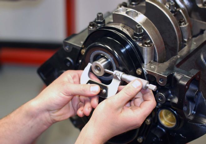 Next we check the size of our crank end. We want the snout of the crankshaft to be 0.0008-0.001 larger than the ID of the dampener bore.
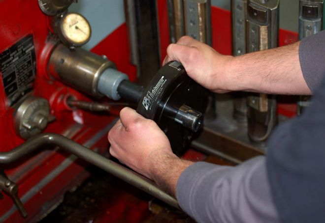 If the damper bore needs to be enlarged, we use our Sunnen honing machine to hone the bore for the proper press fit of 0.0008-0.001.
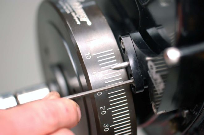 Once the camshaft endplay was set, the cam cover bolted on, and our dampener installed, we needed to set our timing pointer to true TDC before we install the cylinder heads. We do this by putting a dial indicator on number one piston and rotating the engine till the piston is at its highest point (closest to the deck) then adjust the pointer to “0” on the dampener.
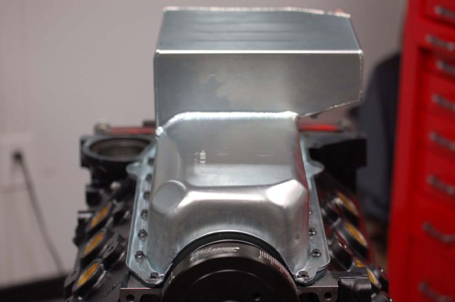 After setting the camshaft endplay, installing the dampener, and setting the timing pointer, it was time to install the oil pan to contain any oil dripping down from the installation of the top end components. But before we do that, we first have to check the oil pump pickup depth to ensure that we have 1/4- to 3/8-inch clearance to the bottom of the pan. Once that’s done, we then TIG-weld the pickup to the oil pump and install it on the rear main cap and torque it to 65 pounds with moly lube. Not until all those things are done can we put our Cometic one-piece oil pan gasket on and tighten things up.
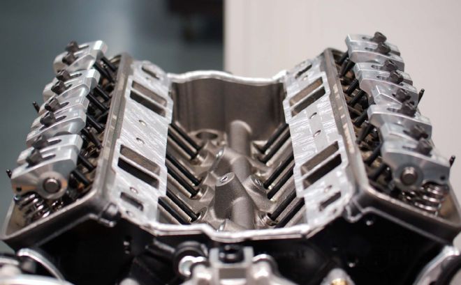
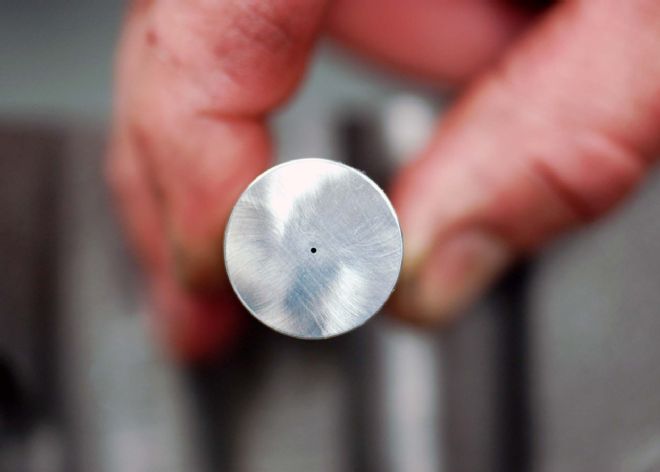 As you can see here, our Erson pro-duty solid lifters come with a 0.012-inch EDM hole in the center, the hole provides a direct stream of oil for the camshaft interface and will let us run higher valvespring pressures without having to worry about a lifter getting damaged.
 The lifters and bores are coated with Klotz assembly lube before we install them in the block. The cam has already been lubed prior to installing it into the block as well.
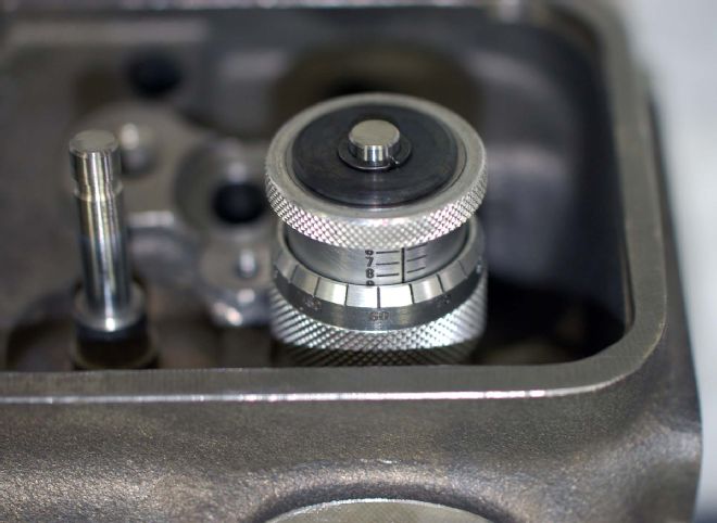 Before we can put the heads on we have to build them, all the cylinder head components, including the cam and lifters came from Erson. We needed to establish the installed height of the valvesprings, we use a dedicated tool for this called a height micrometer, with this tool you can measure installed heights to within 0.005. We installed our Erson dual valvesprings at 1.810 with a seat load of 150 pounds for our cam, and an open pressure of 350 pounds.
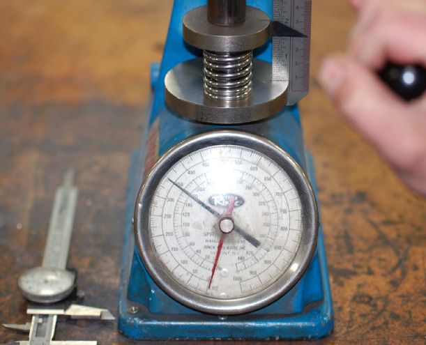 Once we have established our installed height we have to check the entire batch of valvesprings prior to installing them. We do this with a spring tester and we check all the springs at our installed height of 1.810 to ensure they are at 150 pounds closed and 350 pounds open. Properly matching the valvespring to the cam will ensure us that we will not experience any valve float. A weak spring can cause valve float and eventual breakage.
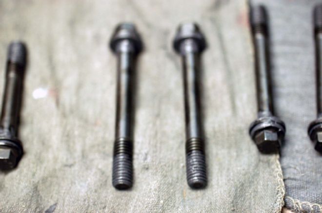 Once all of the valvesprings have been checked and lifters have been installed into the block, we need to mount the heads onto the block. Since our World Products block comes with blind head bolt holes there will be no need for sealer on the threads, so we use ARP ultra lube on the threads and also on the washers, top and bottom. This ensures us that we attain the correct force on each bolt by reducing the friction that might give us false torque readings. The fastener manufacturer has recommendations as to which lubricant to use and often will provide its own lube for this process.
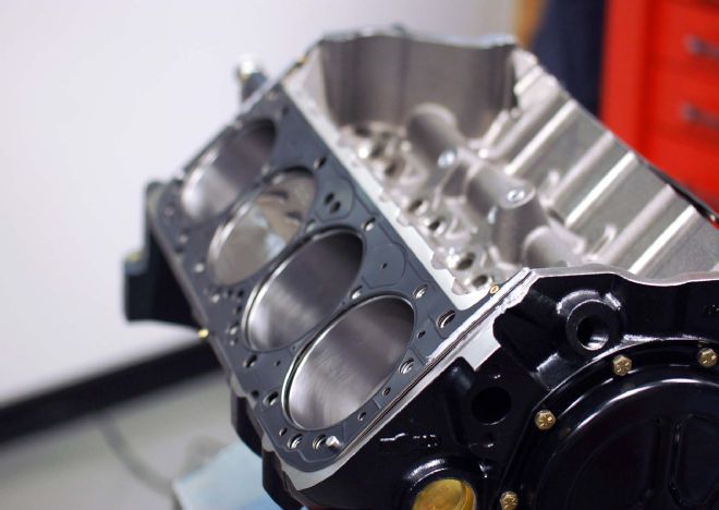 We install the Cometic head gaskets and prepare to torque the heads in place using the routine we previously described below.
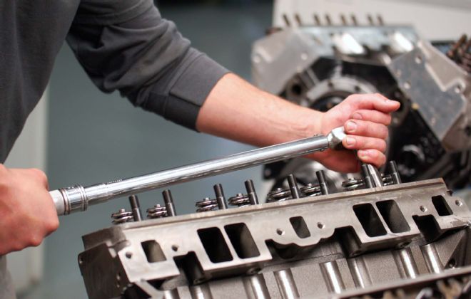 Once the head gaskets are in place, we torque the heads in steps and in a sequence starting at the middle of the head and working our way out in a circular pattern toward the front and rear of the block. Take your time with this process and when using an extension on your torque wrench, support the end of the wrench with your other hand so that the socket remains lined up with the head of the bolt. In order to get an accurate reading on the torque wrench, it must be at right angles and lined up with the bolt at all times. We torque the ARP head bolts to 75 lb-ft with moly lube applied, going to half that amount in the first sequence.
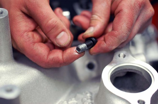
 Before we can put the rockers on we need to install the rocker studs and guideplates; attention to detail is crucial. We want to make sure the roller tip contacts the valvestem exactly in the center, we move from cylinder to cylinder one at a time and adjust the guideplate with the rocker arms just set in place. There is no wrong way to do this and “sighting” them in works fine.
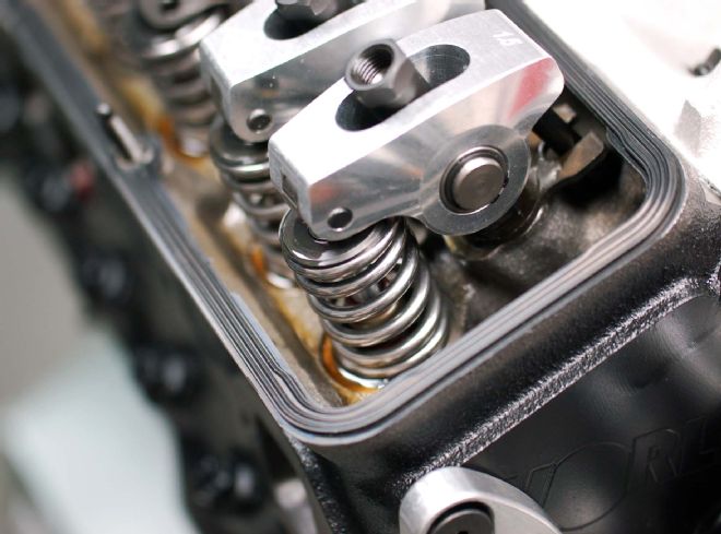 With the correct length push rods installed we can mount the valvesprings and rocker arms and prepare to set the valve lash or gap. For each set of rockers, make sure that the cam is in a position where both valves are closed before tightening the rocker nut. Then bring the nut down until the rocker roller just touches the end of the valvestem.
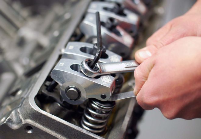 Now we can set the valve lash. The procedure we use to ensure that each lobe is on the base circle is as follows: we do one cylinder at a time, rotate the engine until the exhaust valve on the cylinder you’re working on just starts to move. Now adjust the intake valve. Once the intake valve has been adjusted, rotate the engine. Watching the intake valve until it goes to max lift, continue rotating past max lift and stop halfway from the intake valve being closed, now adjust the exhaust valve, using this method will ensure you that you are always on the base circle, then move to the next set and repeat until all the valves have been adjusted. For this build, we set both intake and exhaust valve lash at 0.015. Once the engine has been brought to temperature the cam manufacturer wants 0.020 HOT.
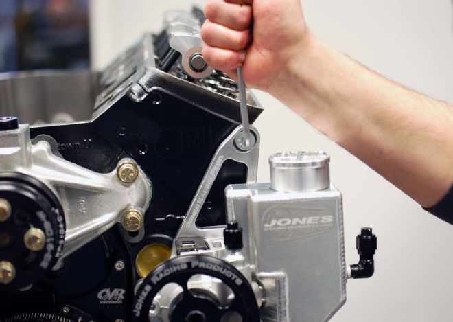
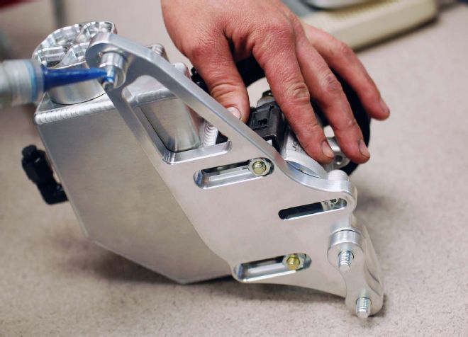 Once our heads and oil pan have been installed, we can mount the components to the front of the motor using the Jones Racing brackets. Note that the bolts are recessed and the slots are sized to the bolt head. These mounts are fully adjustable for positioning a variety of components.
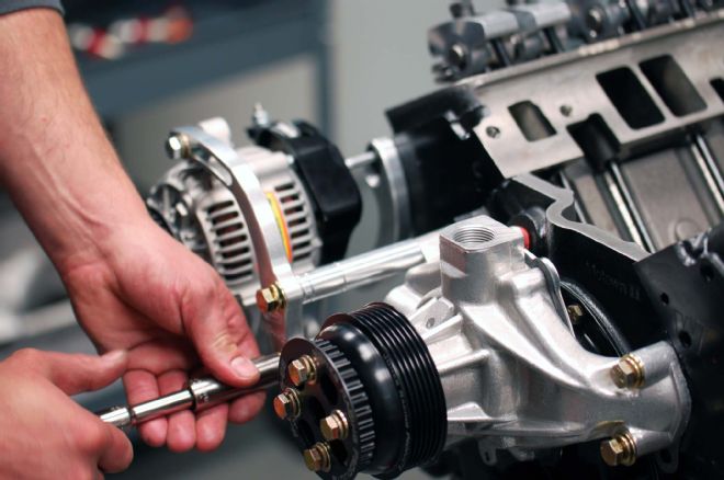 The water pump is installed along with the brackets for the alternator and any other components you will be using. Take your time and inspect all of the threaded holes in the block to make sure they are blind holes. If any of them protrude into any of the block cavities, you will need to apply sealant to the ends of the bolt.
 The car our engine will be installed into will have power steering, so we install the PS pump with brackets supplied by Jones. We use blue Loctite on the fasteners so nothing comes loose.
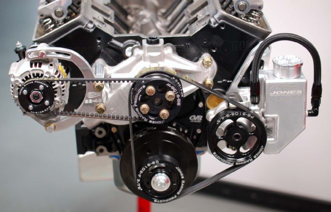 Here is how the front of the motor looks with the completed assembly. This is a neat and compact package that goes together well. Once we install the valve covers, plugs, and plug wires, carburetor, and fuel pump, we will be ready to move over to the shop dyno for a first run.
 With the water pump and other brackets in place, we can now install the intake manifold. First place the intake gaskets carefully onto the heads, making sure the bolt holes line up and then that the intake runner openings are without overlaps. We apply a silicone sealer to the edges of the block under the ends of the manifold to provide a good seal. Then we are ready to place the manifold.
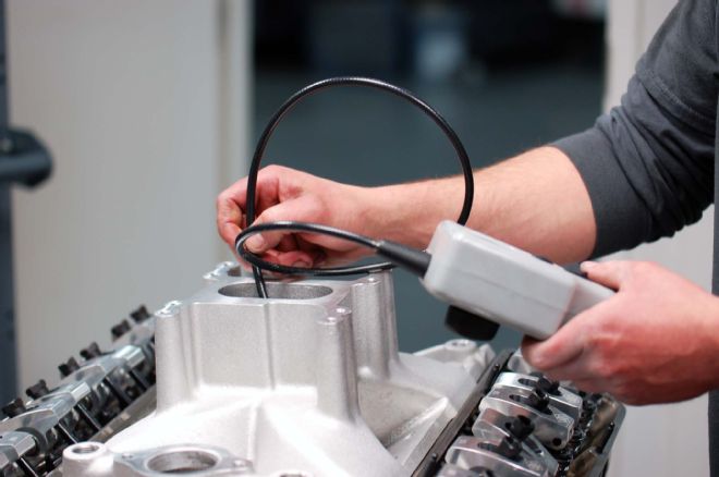 Once we have carefully placed the manifold onto the heads, we use a bore scope. Some intake manifolds are difficult to see the port alignment; the bore scope works to visually inspect the runners to see if the fit between the intake runners line up with the openings in the heads. There is no way to really know this until the intake has been put in place with the correct gaskets. We need to know that the flow of our air/fuel mixture will not be disturbed by a misalignment of the intake manifold and the heads.
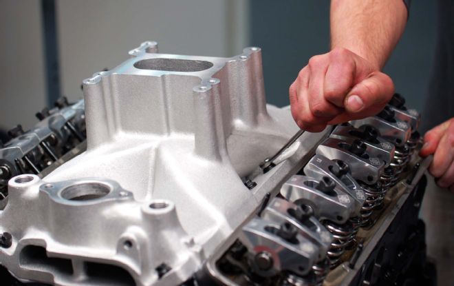 Once we are sure there are no problems with the alignment of the intake manifold, we apply sealant to the bolts and bolt it down to the heads.
 We use a sealer on the all of the intake manifold bolts. This keeps oil from migrating up the bolts and possibly puddling on the intake as some bolts are open to the inside of the head.
 This tool will be used to determine the correct depth for the distributor so that the distributor gear will mesh correctly with the cam gear. Distributor gear life depends on a correct alignment. The tool not only lets you check the distributor gear mesh, you can also check the intermediate shaft for the oil pump as well as prime the oil system prior to startup.
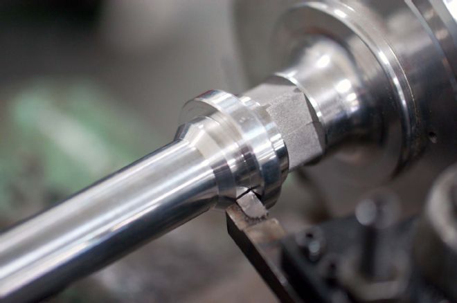 Once we have determined the correct depth for our DUI distributor from our tool, we can duplicate that dimension. This is a very important step and the height changes depending on how much material was decked off the heads and block. You can see here we had to remove some material in the lathe to get our gear to be in the center of the cam gear perfectly. Some distributors come with an adjustable collar that makes this easier but you still need the tool to know which way you need to go.
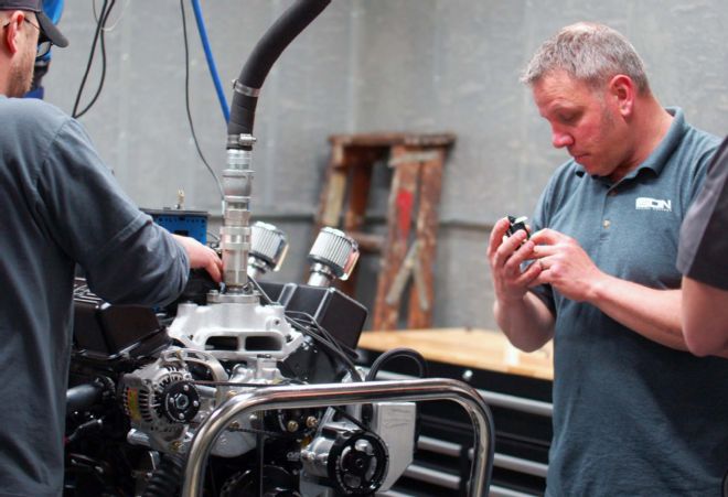
After we performed the break in, it was time for some tuning. Here I’m looking at the bleeds that are in the emulsion circuit. We are trying to optimize our air/fuel ratio for max power. The water supply is up and out of the way on our dyno design and this provides more room to move around the motor and provides access in case there is a leak.
Once we have determined the correct depth for our DUI distributor from our tool, we can duplicate that dimension. This is a very important step and the height changes depending on how much material was decked off the heads and block. You can see here we had to remove some material in the lathe to get our gear to be in the center of the cam gear perfectly. Some distributors come with an adjustable collar that makes this easier but you still need the tool to know which way you need to go.
After we performed the break in, it was time for some tuning. Here I’m looking at the bleeds that are in the emulsion circuit. We are trying to optimize our air/fuel ratio for max power. The water supply is up and out of the way on our dyno design and this provides more room to move around the motor and provides access in case there is a leak.
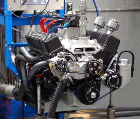 The motor ran very well throughout the break-in period and with a little timing and carburetor jet tweaking, produced 455 hp at 6,000 rpm and a stump pulling 462 lb-ft of torque at 4,700 rpm. Now we can install the motor into the car and do some chassis dyno runs.
World Products
877/630-6651
www.pbm-erson.com
PBM Performance
800/588-9608
www.pbm-erson.com