It's never been easier for the homebuilder to assemble an engine than now. Thanks to the availability of premachined engine blocks and matching rotating assemblies from folks like Summit Racing, a guy can literally skip the wait at the local machine shop and ensure that his engine components are spec'd to the highest degree necessary.
Building a solid street engine isn't rocket science, but there is a bit of math involved in order to optimize the performance and reliability of said engine. Whether you're going with the aforementioned path and buying a machined block and matching components (like we'll be doing with our 383 engine build in the near future) or you've farmed out a used block to the local machine shop and had them machine it to match your chosen components, it's a good idea to measure everything before it all goes together.
One time-honored method to measuring bearing clearance was to use Plastigage. A strip of the colored stuff is placed in between the bearing and the crankshaft and the assembly is then torqued to spec. It's then disassembled and the compressed Plastigage strip compared to the product's provided scale. The result is then compared to the specs determined by the engine's machine shop and judged as to whether or not the assembly is acceptable.
For most street-driven, moderate-horsepower applications, this process is totally satisfactory as it's only double checking the clearance that should have been machined into the assembly to begin with; it's strictly done to ensure that the parts have been machined to the specs determined by the machine shop before assembly. It's a failsafe step and by far the simplest way to determine safe bearing tolerances, be they crank or rod.
Taking this process a step further requires the use of a few specialized tools. First, the crank main bearing journals are measured using a micrometer. The micrometer is then installed in a vise so that a dial bore gauge can be installed and zeroed to the crank journal's diameter. Next, the dial bore gauge is inserted in each of the main bearing journals on the block (with the bearings installed and the caps torqued to spec) and the bearing diameter noted. The difference between this measurement and zero on the dial indicator is the bearing clearance. Checking each bearing assembly using this method allows the builder to note the exact clearance and adjust the tolerances to suit (installing over- or undersized bearings for example).
Using this process ensures that each measurement is determined within the confines of the mic's ability to accurately measure the crankshaft's journal. It is possible to yield the same results by measuring the crank journals using the mic and comparing that number with readings taken from each bearing via the dial bore gauge and comparing the two. The problem with this method is that if either or both tools are out of spec a few thou, your clearance number will be affected and incorrect. By setting the dial bore gauge to the mic, it doesn't matter whether either tool is out of spec as we're only measuring the difference of the two via the dial indicator. Provided the measurements are taken correctly, it doesn't matter what the actual measurement of either the crank journal or the bearing assembly is as we're only concerned with the difference or clearance.
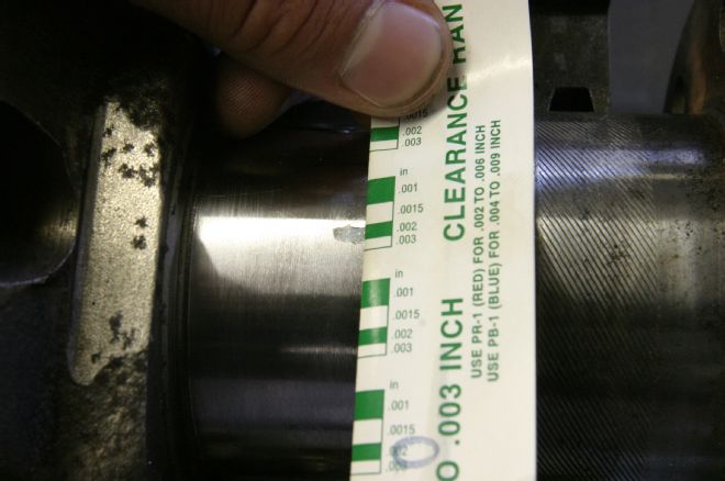
01 Here, the traditional method of measuring bearing clearances using Plastigage is shown. This crank/bearing assembly yielded an acceptable 0.002-inch clearance, noted by comparing the crushed wire to the provided chart.
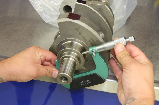
02 Using the more technical method, first we measure the crank journals using a micrometer.
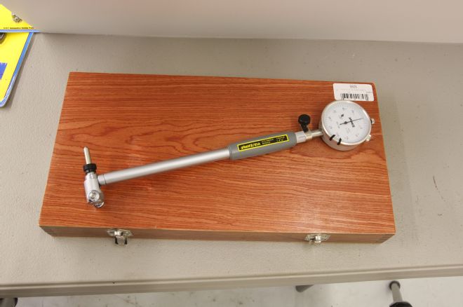
03 We'll be using a dial bore gauge to check the tolerances of both the main bearings as well as the rod bearings when we get to the rotating assembly. Powerhouse Products makes this example, which can measure diameters from 1.4 to 6 inches by swapping out the various anvils and indicating spacers.
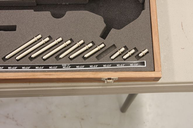
04 We'll be using a 2.6-inch anvil in the bore gauge to measure the crank bearing clearances.
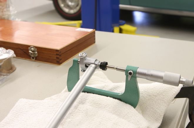
05-06 With the micrometer installed in a small vise, the dial bore gauge is zeroed to the crank journal's size.
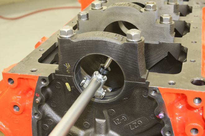
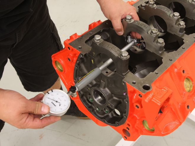
07 Next, the dial bore gauge is used to measure the diameter of the main bearing assembly. Here, we're measuring the assembly as machined with the stock main cap bolts torqued in place.
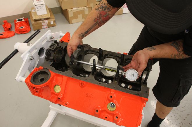
08 We're going to supercharge our engine, so we opted to install a set of ARP main cap studs to keep the crank in the block. Though our block was align honed, it was done so using the stock main cap bolts. Since the clamping forces can change when swapping out cap bolts for studs, it's necessary to check the tolerances with the main studs installed and torqued to spec.
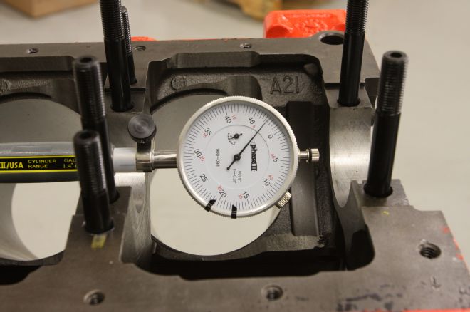
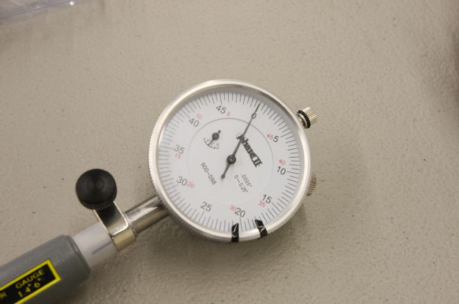
09 Notice the difference between the dial bore gauge's reading and the zero mark? That's our bearing clearance; 0.0025-inch. Exactly where we want it to be.