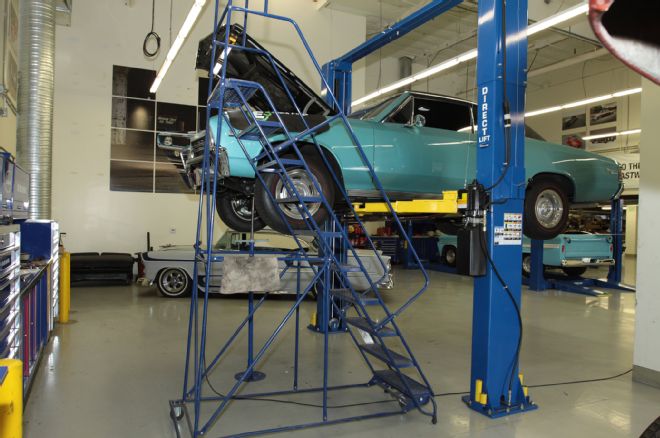
Right from its very beginning as what most would declare an unsalvageable rusted-out hulk, the 1967 SS396 Chevelle known as the AMD Chevelle was destined to become Super Chevy’s test mule for evaluating a plethora of aftermarket options. In the future, readers can look forward to anything from modernizing the AMD Chevelle’s interior to searching out the most effective modifications to be made to its big-block 402, punched out to 413 inches.
In this installment the focus is on the big-block’s top end and we were able to take a one-modification at-a-time approach thanks to it already having a hot cam in place. In simplified terms, the significance of a hotter cam with more lift and duration is its ability to fully utilize cylinder heads with greater flow characteristics. In short, if we left the stock cam in place and installed better flowing heads first there would be less of an improvement noticed. And, of course, since any claims of improved flow without supporting documentation is unsubstantiated baloney we have included the flow sheet data we obtained from Westech Performance Group in Mira Loma, California.
In addition to obtaining the flow bench results comparing the two different cylinder heads we were able to pull a baseline dyno run at Westech on the AMD Chevelle before the new Edelbrock E-Street 290 heads were installed. Please stay tuned for the next installment where we’ll reveal the AMD Chevelle’s before and after dyno results.
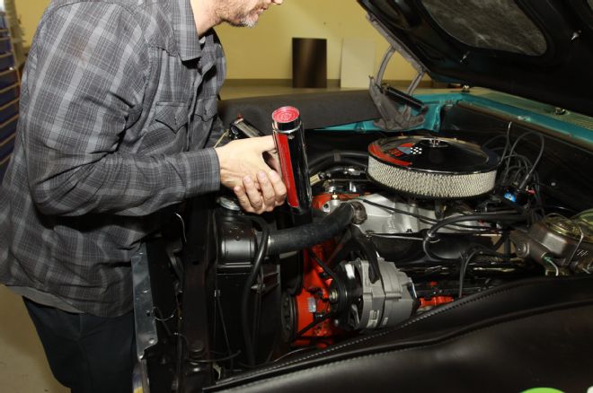
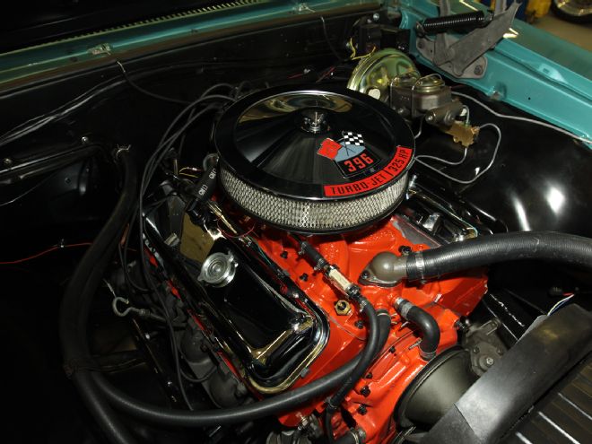
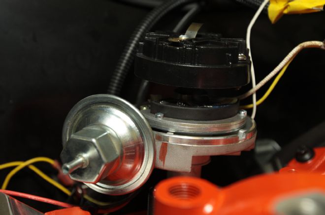
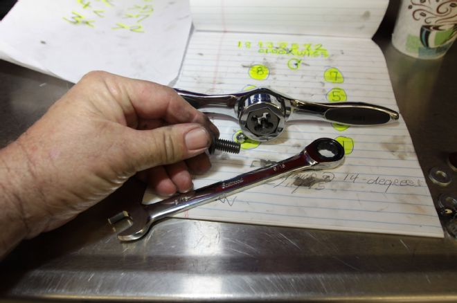
1. The Chevelle ran great where the timing was at, so before tearing the 413’s top end down we hooked up a timing light to make note that the timing was set at 14-degrees BTDC.
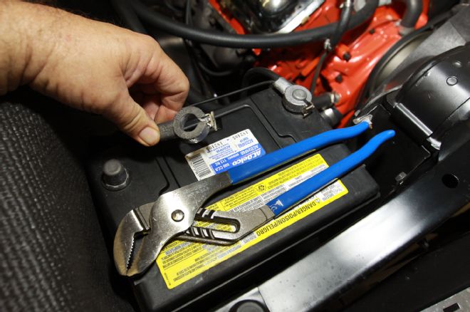
2. To prevent unexpected moments of spark filled pyrotechnic excitement it’s always a good idea to disconnect the battery before proceeding further.
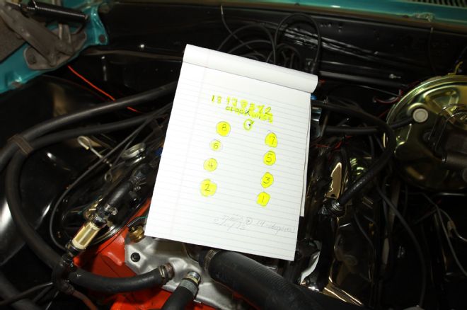
3. Drawing a chart with the firing order and cylinder location clearly marked was a big help throughout the job, as was writing down notes.
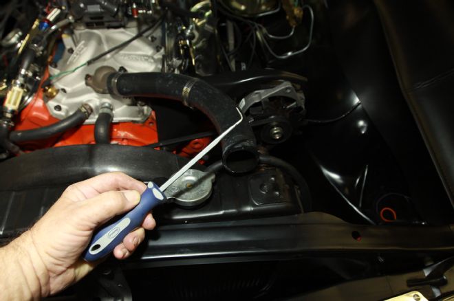
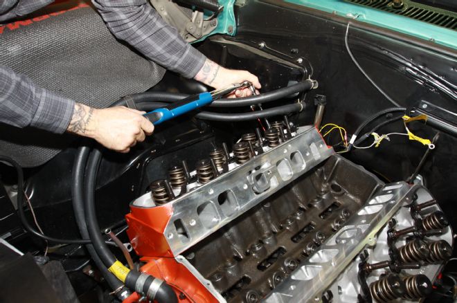
4. A lot of time during the teardown process can be lost to silly, inconsequential things like removing radiator and heater hoses. This Eastwood glass tool, along with a spray lubricant, made short work out of removing stuck hoses.
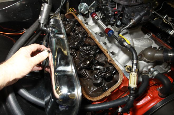
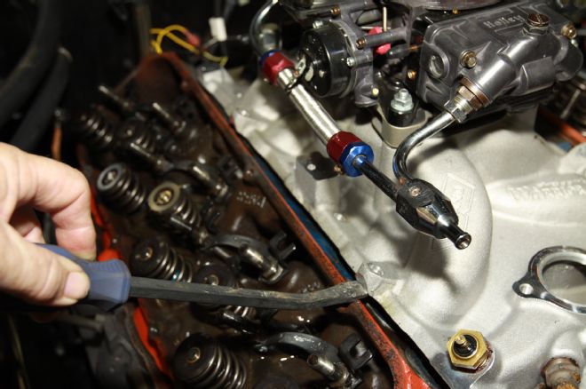
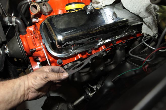
5. Notice in the lead photo this leaky red and blue anodized dual-feed fuel line was replaced with black EFI hose. It’s a wonder why the rocker arms are half stock pressed steel and half roller-tip.
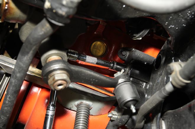
6. To capture the timing or to prepare it to set the initial timing the crankshaft was brought to top dead center (TDC).
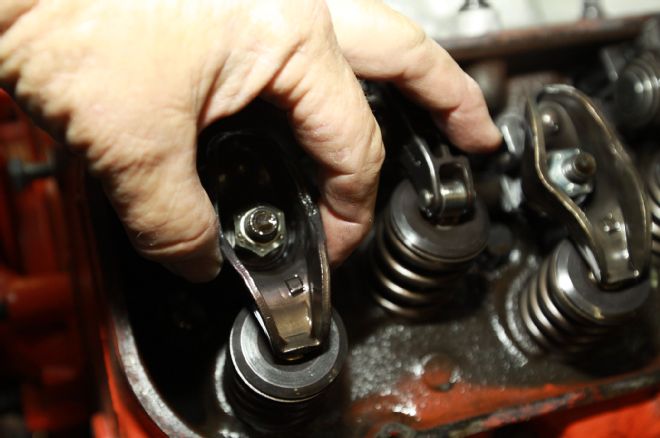
7. To ensure the timing was not 180-degrees out, we noted number one intake and exhaust valves were fully closed (no load on rocker arms).
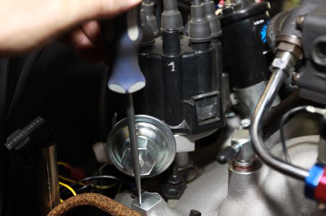
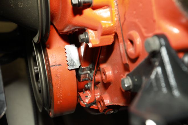
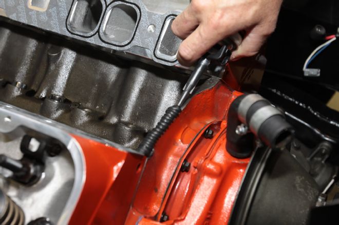
8. A strong scratch awl was used to center punch a mark on the intake manifold aligned with the vacuum advance module showing where the distributor was pointed at 14-degrees BTDC.
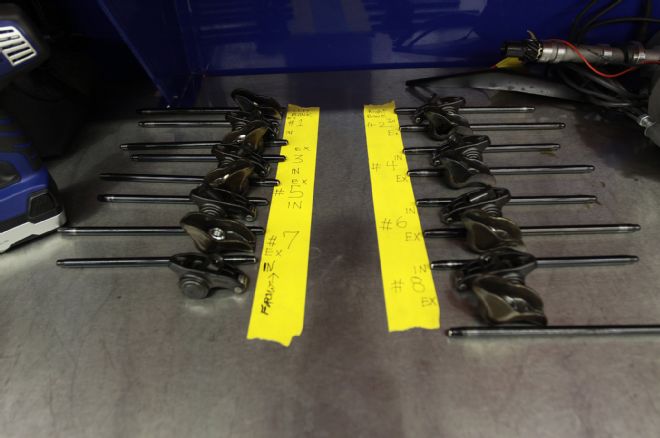
9. There was just 2,000 miles on this new valvetrain. Wear patterns; if the parts are to be reused it’s a good practice to number where they came from so they can be put back in the same place.
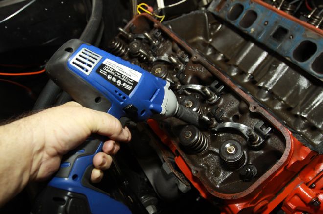
10. An electric or pneumatic impact wrench makes short work of disassembly.
11. Intake manifolds are usually stuck on pretty tight; ours was really tight. We looked for an area on each side at the front and rear to pry on without blemishing the aluminum.
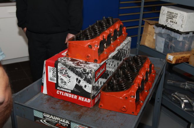
12. The stock cast-iron 396 Chevrolet 325-horse heads weighed in at 75 pounds. The Edelbrock E-Street aluminum heads weigh about half as much.
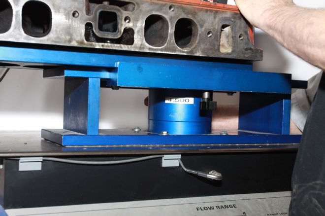
13. A larger bore than the 413, the flow bench was set to measure at the industry standard 4.5-inch bore.
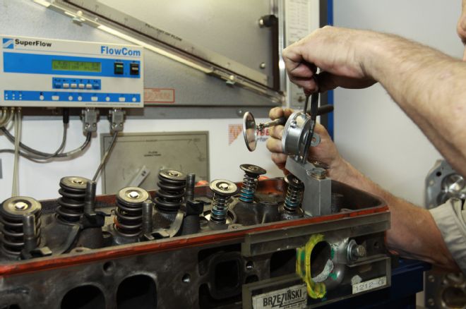
14. Although Westech’s Steve Brule measured flow up to 0.800 inches there’s no need to be concerned regarding flow after 0.600.
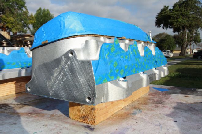
15. We masked off the heads and intake manifold’s ports and oil galleys to ensure paint would not reach unwanted areas and then flake off into oil passages later.
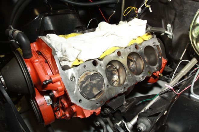
16. For the head gaskets to properly seal, the deck must be absolutely free from leftover gasket material, carbon, and/or rust. Notice the valley has been covered with towels to prevent debris entering the valve lifters and oil galleys.
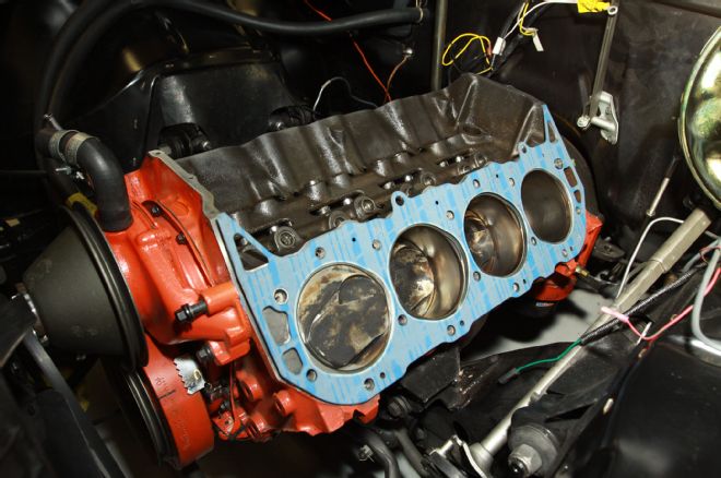
17. We observed the head gaskets have a top and bottom side and installed the head gaskets dry without any sealant over the two locating dowels on the deck.
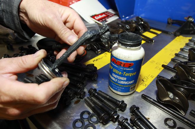
18. Head bolt prep: What’s not shown here is the amount of wire-wheel brushing on a bench grinder it took to remove leftover Teflon sealant. Water jackets be dammed this time around. We applied ARP Ultra-Torque without Teflon sealant and we’ll see what happens.
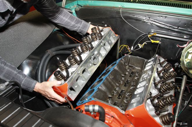
19. The lightness of an aluminum head over cast-iron turns installing the heads into a one-man job. The target was to match up the head with the locating dowels on the deck.
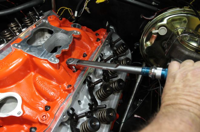
20. I’ve always torqued heads in three steps up to the specified torque, but this time around we went from snugged down right to the specified torque. Again, it’s a wait and see, experiment.
21. Using too little sealant, especially at the rear of the intake manifold, is an oil leak waiting to happen. We applied a 1/4-inch thick bead of Permatex Ultra Black 82180 sealant. Afterwards, the pushrods were dropped in place.
22. The Edelbrock top end gasket set (PN 7363) included head and intake manifold gaskets. We applied Gasgacinch to the cylinder head side of the intake gasket only. After applying ARP Ultra-Torque on the threads the intake was torqued to spec.
23. Initial timing was set at TDC with the rotor pointing to the number one cylinder and then advanced to align with the mark center punched on the intake manifold.
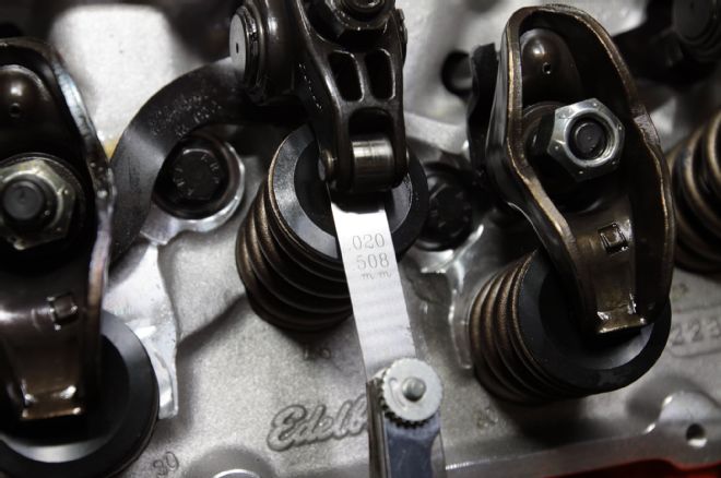
24. To properly adjust solid lifters, the exact opposite valve must be at full lift. For instance, with number 6 intake at full lift, number 1 intake can be adjusted. Ditto for exhaust valves.
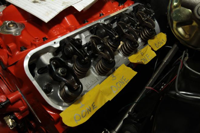
25. Marking the valves as they were adjusted eliminated redundancy. Extreme care was taken not to cross-thread the 1/4-20 valve cover bolts during installation.
26. Big-block Chevelles are tight on the driver-side bank for exhaust manifold clearance. The engine mount bolt was removed and the engine jacked up on the driver-side oil pan rail to gain clearance.
27. Installing the driver-side exhaust manifold could have been done from the ground. After putting the manifold into its place the car was lowered to the ground.
28. Extreme care should be taken not to cross-thread (strip) the aluminum threads. We ran a die over the exhaust manifold bolts and coated them with ARP Ultra-Torque before installation.
29. The exhaust manifold gasket is slotted at front and rear. We installed the front and rear bolt to hang the exhaust manifold onto the head and then slid the exhaust manifold gasket into place. The head pipes were hooked up and the job was done.
GM Cast-Iron Oval Port Closed Chamber Heads (Casting number 3964290) Intake Valve Valve Opening CFM Test Pressure 0.05 31 28” 0.1 61 28” 0.2 127 28” 0.3 190 28” 0.4 233 28” 0.5 255 28” 0.6 263 28” 0.7 265 28” 0.8 261 28” Exhaust Valve Valve Opening CFM Test Pressure 0.05 25 28” 0.1 51 28” 0.2 92 28” 0.3 114 28” 0.4 135 28” 0.5 151 28” 0.6 168 28” 0.7 178 28” 0.8 182 28”
Edelbrock E-Street 290 Oval Port Semi-Open Chamber Heads Intake Valve Valve Opening CFM Test Pressure 0.05 32 28” 0.1 66 28” 0.2 119 28” 0.3 149 28” 0.4 172 28” 0.5 191 28” 0.6 204 28” 0.7 214 28” 0.8 220 28” Exhaust Valve Valve Opening CFM Test Pressure 0.05 28 28” 0.1 56 28” 0.2 119 28” 0.3 149 28” 0.4 172 28” 0.5 191 28” 0.6 204 28” 0.7 214 28” 0.8 220 28”