There is a long list of considerations when turning an ordinary vintage pickup into a custom classic truck. Some are cosmetic, others are for performance, and there are often safety issues as well. In this particular case, all three are factors.
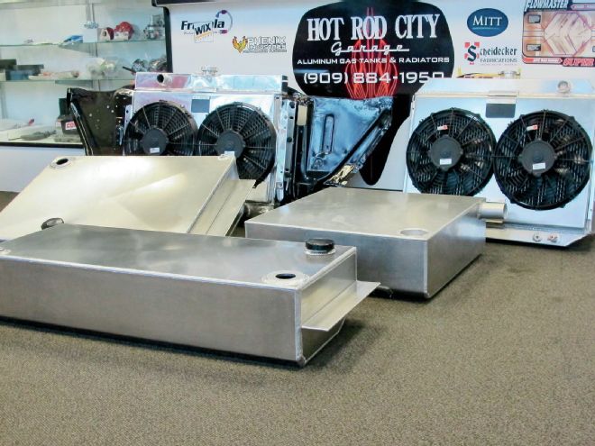
When our own Source Interlink Tech Center manager, Jason Scudellari, had to come up with a fuel tank for his '56 Chevrolet pickup he wanted one that was good looking, housed an in-tank electric pump, and was mounted outside the cab under the bed. To get everything he wanted Jason turned to Hot Rod City and Aeromotive.
Hot Rod City specializes in custom aluminum radiators and fuel tanks for GM, Ford, Mopar cars and trucks and can build one-offs for virtually any vehicle. All tanks are fully baffled and include mounting straps (if used) and the necessary bungs.
To pump fuel from the tank to the engine Jason elected to go with Aeromotive's unique Phantom 340 Stealth Fuel System.
With Aeromotive's in-tank system the pump is submerged in fuel, which means it will run cooler and will last longer and be quieter as well. The 340 series pumps can be used with fuel injected or carbureted engines and will support up to 700 horsepower with EFI and 1,000 horses in carbureted supercharged applications. A unique feature of Aeromotive's Phantom Stealth system is it can be installed in virtually any fuel tank with a depth of 5.5 to 11-inches deep (a special baffle/basket assembly is available for deeper tanks).
While the Hot Rod City crew was busy fabricating his new gas tank and installing the Aeromotive pump, Jason was banging away with his camera to document the procedure. Here's how it was done.
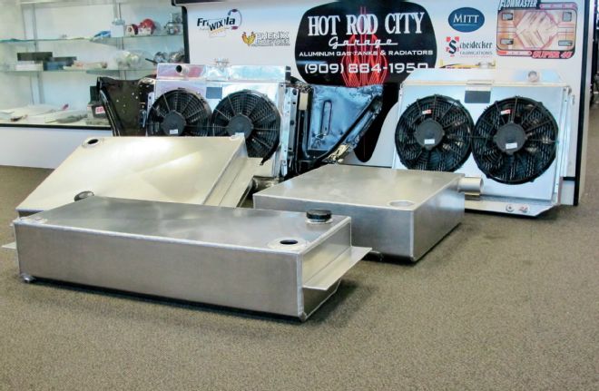
1. Hot Rod City specializes in custom aluminum gas tanks, radiators, and fan shrouds. They also maintain a fully stocked retail store.
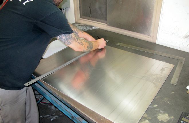
2. The first step in construction is to lay out the components on a sheet of .090-inch 5052 skinned aluminum.
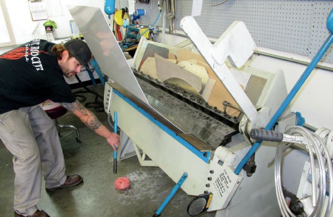
3. Cut to size, the front, bottom, and back of the tank are formed from one piece in a brake.
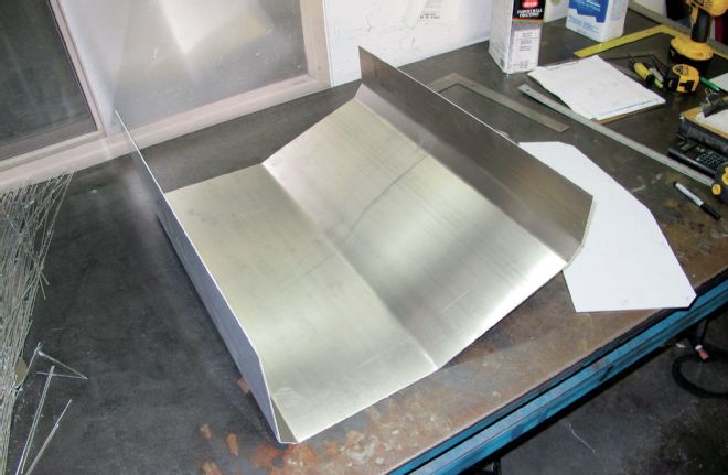
4. By forming the bottom and end panels from one piece a considerable amount of welding is eliminated.
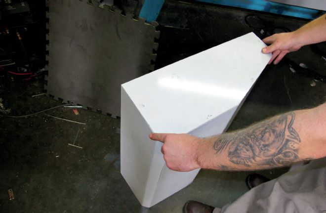
5. Next, the sides are cut to fit. So it doesn’t look like a big aluminum box from the rear of the truck, the bottom of the tank angles up at the rear providing a rolled pan look.
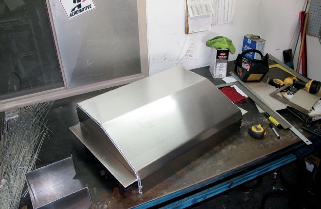
6. Here, the bottom and sides are tack welded together and half of the mounting tabs have been added.
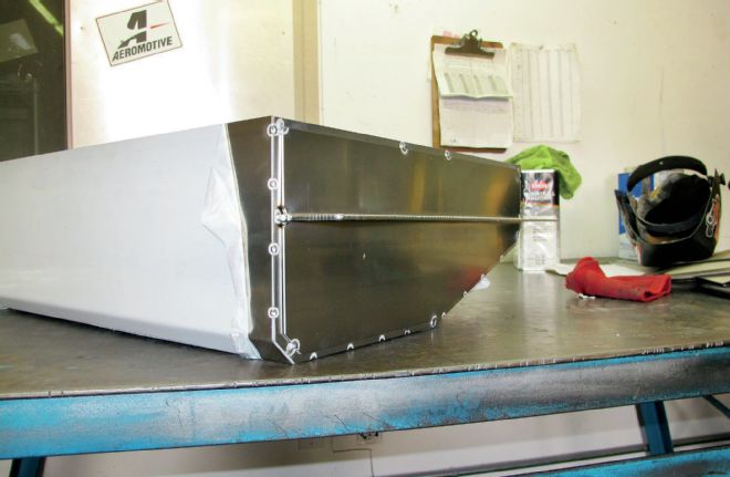
7. Note the sturdy upper and lower pieces of the mounting bracket have been welded together to make a strong, double thickness flange.
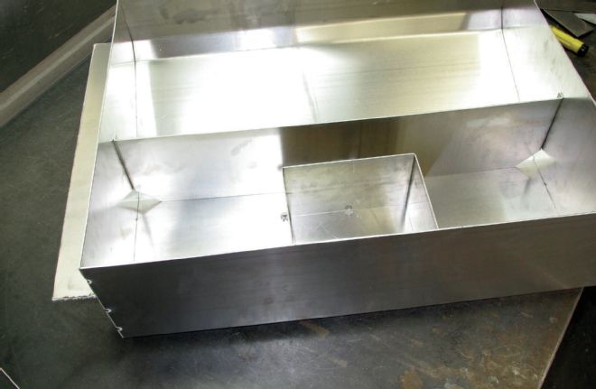
8. Viewed from the top, the main interior baffle and the sump for the electric fuel pump can be seen. Note the notches in the lower corner of the baffle allow fuel to equalize on both sides.
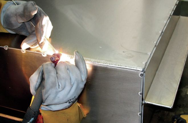
9. All the seams are TIG welded. Note the consistency of the bead—that takes talent.
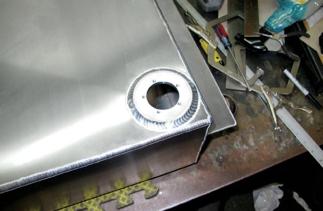
10. This is the flange for the fuel level sender. Stock or aftermarket senders can be specified.
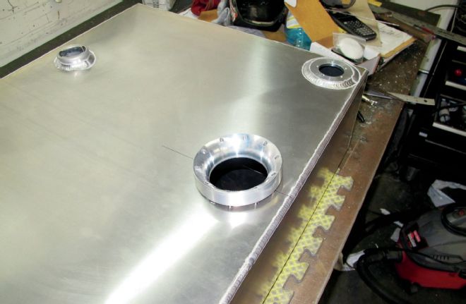
11. A variety of filler neck and cap options are available. In this case the cap will be accessed through a door in the bed floor.
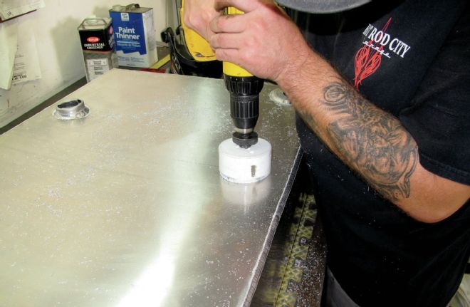
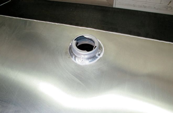
12. The first step to installing the pump and pickup is making an opening with a hole saw.
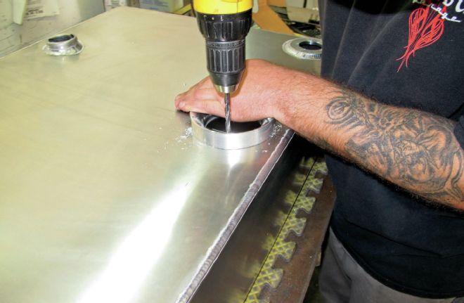
13. With the opening cut, a guide is put in place to drill mounting holes for the pump. This guide will also be used to install the foam basket the pump fits in.
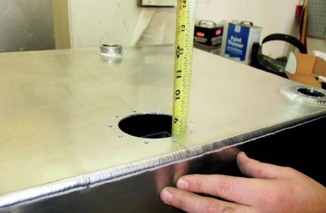
14. With the tank cleaned of debris from drilling, the depth of the tank is measured so the pump bracket and the baffle/basket assembly can be cut to the proper length.
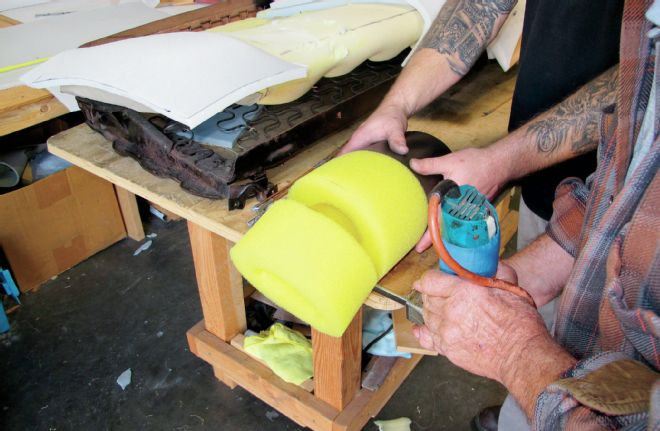
15. Here, the foam baffle is trimmed to length. The black portion at the bottom acts as a sump to keep the pump supplied with fuel.
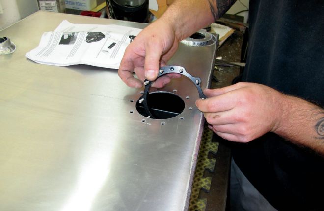
16. This is the split ring that has studs to secure the pump bracket/pickup assembly to the tank. With the studs sticking up through the tank it stays in place.
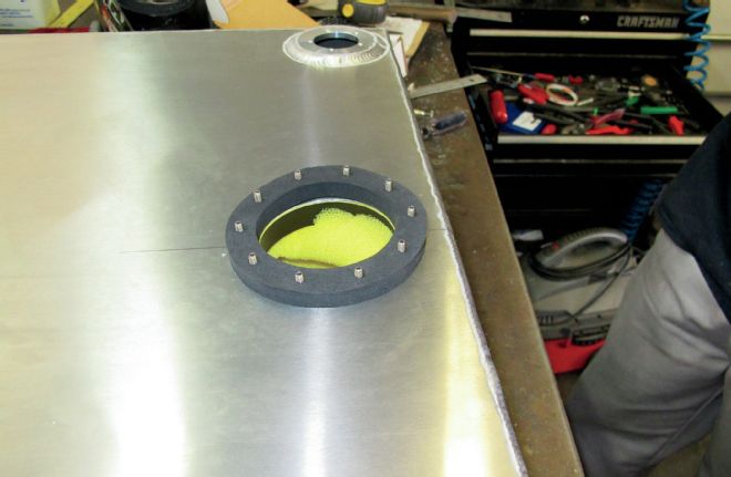
17. With the studs protruding from the tank the drill guide is put back in place.
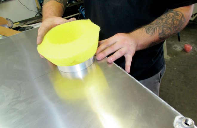
18. The rounded edges of the drill guide make it easy to install the foam basket without damage.
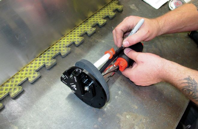
19. With the depth of the tank known, the pickup tube can be cut to position the pump properly.
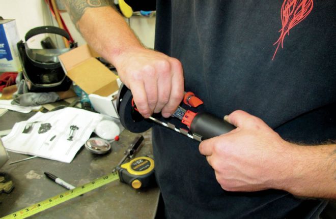
20. After the mounting bracket is cut to length the electrical lead is plugged into the pump.
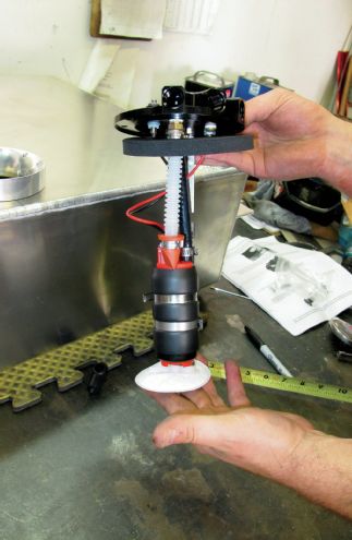
21. The Aeromotive 340 fuel pump is slipped into a foam sleeve, attached to the inlet tube then secured to the pump with hose clamps. The short, white tube is the fuel return.
22. To prevent seepage before the pump assembly is installed a thick gasket is slipped over the studs.
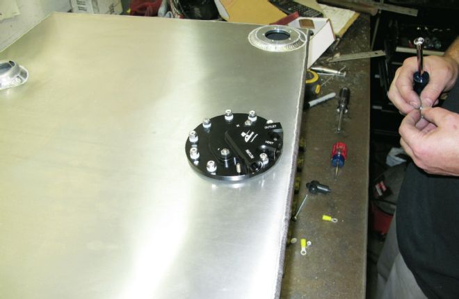
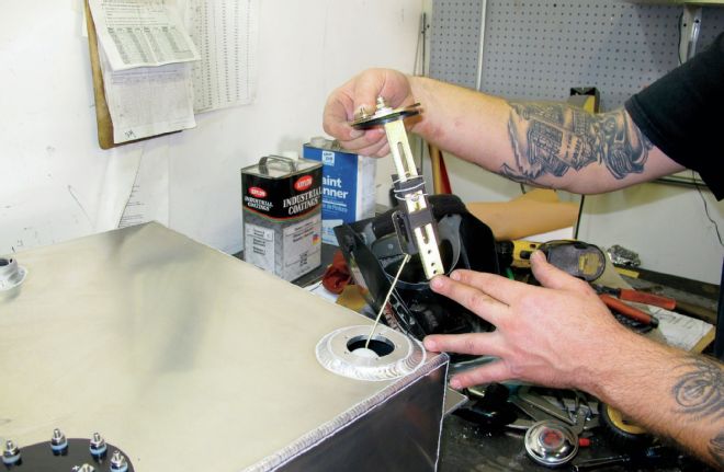
23. The pump and pickup is simply dropped in place and secured with the included lock nuts. The outlet, vent, and return connections are ORB-06. Plus and minus connections are power and ground for the pump.
24. After adjusting the fuel level sender for the depth of the tank, it was put in place.
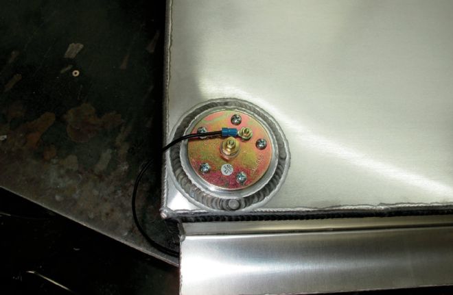
25. The fuel sender has two electrical connections. The center stud is for the wire from the gauge; the other connection is for a ground wire, which should be run to the frame as there is normally an insulator of some sort between the tank mounts and the frame.