We are elbow-deep into our latest engine buildup project, a salvage-yard ’66 Pontiac 421 V-8. So far we have taken the engine apart to gauge its soundness (“The Teardown,” Mar. ’14) and run the block through Jaime Gonzalez’s Precision Engine Development shop in South El Monte, California, to make sure it was square and true (“Block Machining,” Apr. ’14).
With the bare block safely stored in a plastic bag, we now turn our attention to the other engine components slated for rejuvenation: the heads, valves, rods, and crankshaft. We again turned to Gonzalez to complete all of the work on these components.
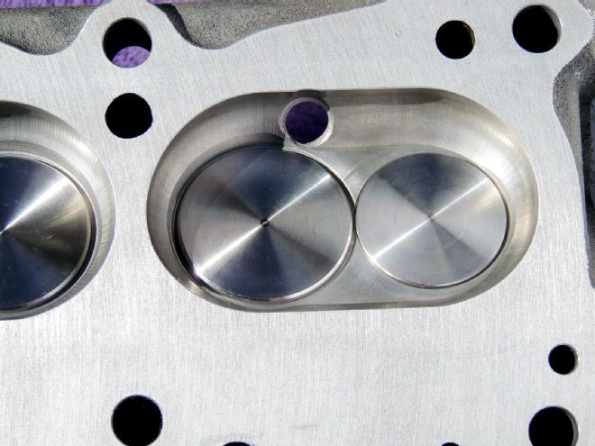
The heads that were on our single four-barrel 421 are known as 092 heads. These heads were also used on all ’66 389ci GTO engines. They featured 70cc combustion chambers resulting in a 10.75:1 compression ratio for the 421; 10.5:1 for the 389. The valves had diameters of 1.92 inches on the intake side, 1.66 inches on the exhaust side. The combustion chambers are machined—a nice bonus. A downside to these heads is that there is no room for bigger valves. For the ’67 model year, Pontiac solved that problem by redesigning its heads with wider-spaced valves, allowing for 2.11-inch intakes and 1.77-inch exhausts. The only other downside to the 092 heads is the restriction to the exhaust due to the porting in the exhaust passage for the air injection reaction (AIR) system.
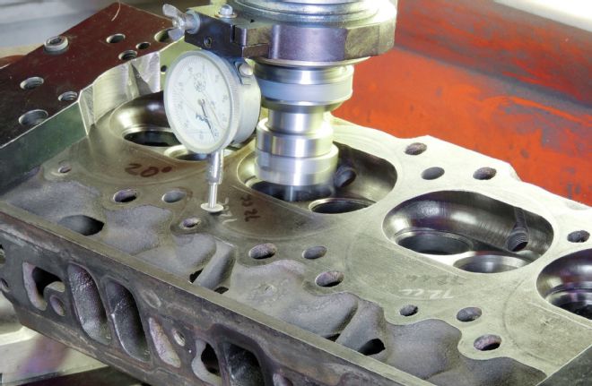
 A 0.002-inch cut has been made on one of the cylinder heads. The brighter witness marks indicate how much the head was warped. It took another cut of 0.003 inch to flatten the surface.
The heads were cleaned, Magnafluxed, and shot-peened. Magnafluxing is done prior to shot-peening as it can hide some small cracks. The heads were mounted in the same mill that was used for the block surfacing. Both of the heads had a slight warp that required a 0.005-inch surfacing. This reduces the combustion chamber by approximately 1 cc. Had this engine been rebuilt prior to our cracking it open, it would have been prudent to check the combustion chamber volume prior to machining in case the heads had been previously milled. The milled surface finish is cut to RA-35, a standard for machined surfaces.
Our luck continues with this engine as all of the valve seats were in good condition. We will not be installing hardened seats because this engine is not going be raced or driven hard. The exhaust seats were machined at 45 degrees and the intake seats at 30 degrees. Because of the close valve spacing, it’s impossible to add larger valves in these heads.
 All of the valve seats were machined to the same specific depth, with intakes cut at 30 degrees and exhausts at 45 degrees.
We are going to install screw-in rocker studs. This required the rocker stud bosses to be milled, drilled, and tapped for the new ARP studs. New bronze K-Line valve guides were installed and honed to provide 0.0012 inch of clearance for the intake valves and 0.0016 for the exhaust valves.
 The openings in the head where the pushrods pass through are also designed to maintain the tip of the rocker arm over the end of the valve. This enlarged opening allowed the rocker to wander, with the results being broken pushrods and worn rocker studs.
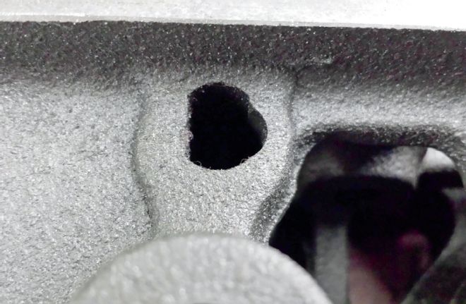
Working with the heads answered a question we’ve had since we disassembled the engine: What caused the busted pushrod and damaged rocker studs? A close examination of the openings in the head where the pushrods come through revealed that several of the slot-shaped openings were too wide, allowing the pushrod to move to the side. They were moving so far that the rocker on one valve would hit the retainer of the adjacent valve. The solution was to bore out all of the pushrod openings and add Isky adjustable guide plates.
Because we are adding a roller cam that requires higher valvespring pressures, we opted for new valves. We could have ground the old ones, but it was cheap insurance to replace them all with new SI stainless valves with hard chrome stems. All of the valves were faced, ground, and lapped, then tested to hold a vacuum. Prior to installation, the Comp Cams valvesprings were tested at their installed height of 1.675 inches and produced the proper pressure of 135 pounds.
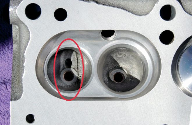 Inside the red oval on this exhaust port, the protrusion for the AIR system can be seen where it creates an impediment to smooth exhaust flow. It’s one of the minor drawbacks to using these otherwise excellent Pontiac 092 cylinder heads. Also notice the slight break on the edges of all of the machined surfaces. This is what a professional machine shop should do as standard procedure.
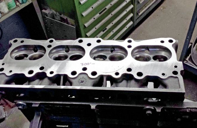
 In this shot of the head, the openings for the pushrods have been drilled out and the bosses for the rocker studs have been milled down 0.400 inch, drilled, and tapped. The larger pushrod openings will require guide plates to maintain valvetrain geometry.
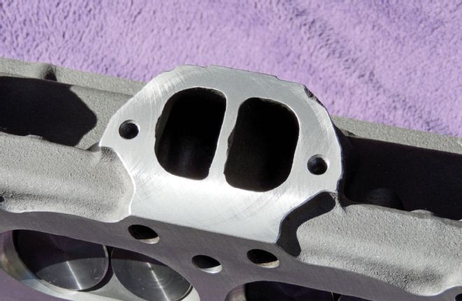 The exhaust manifold mounting surfaces were very pitted. A light pass was made to true them and prevent annoying small exhaust leaks. Again, notice the cleanly chamfered edges on the machined surfaces.
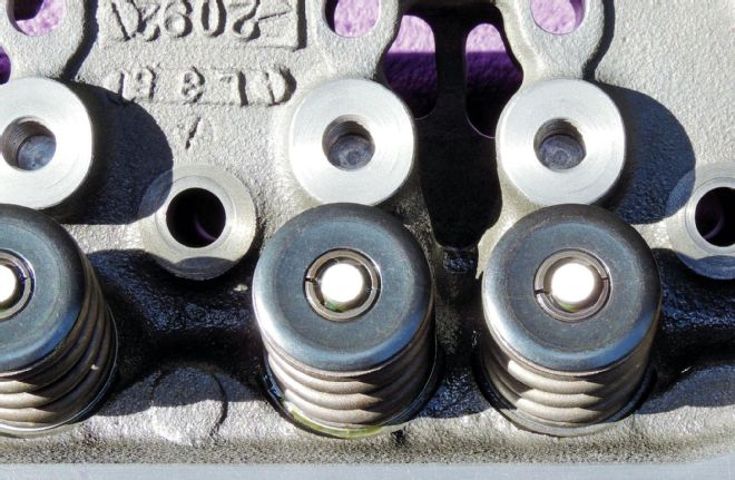
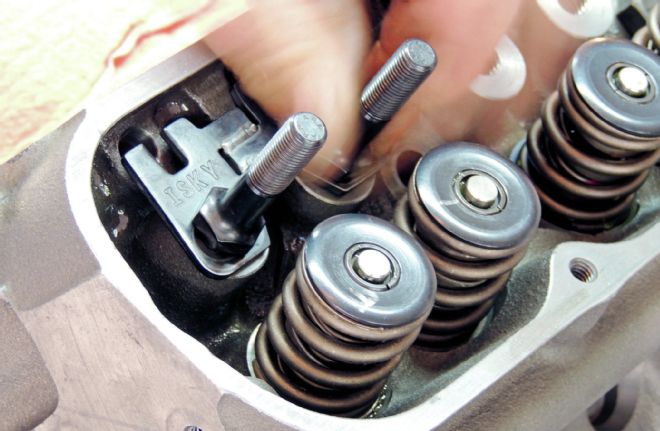 The Comp Cams valvesprings are installed at their designated height of 1.675 inches. The Isky guide plates are designed to keep the pushrods from wandering side-to-side and creating havoc; they are retained by ARP screw-in studs.
We are reusing the original Pontiac Arma Steel rods that came in this engine. Prior to any machining, Gonzalez removed the casting flash from the rods and checked them for straightness. Then the rods and matching caps were Magnafluxed and shot-peened. The big end was resized and ARP bolts were added. The small end was bored and then Clevite bushings added for full-floating piston pins. The rods were balanced in two stages, first by isolating the small end and weighing the big end. Material is removed from the heaviest rods to match the lightest one. Then the entire assembly is weighed with the material removed from the small end until they all match the weight of the lightest rod.
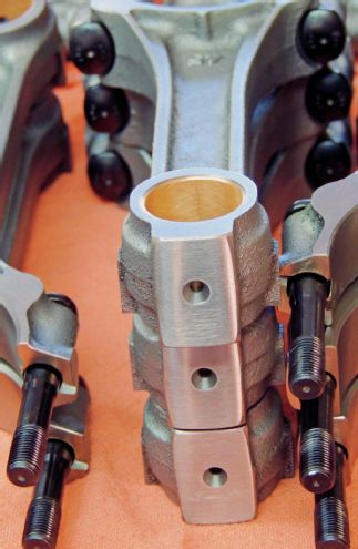 The rods were first checked for straightness, then Magnafluxed and shot-peened. The small end was bored and Clevite bushings were added for the full-floating piston pins. ARP bolts were added for the caps, and then each rod was balanced to within a half gram of each other.
The only forged crankshafts Pontiac used in its 421 engines were in Super Duty applications. All other 421 crankshafts were constructed of a nodular-type cast iron that GM trademarked as Arma Steel. By the sheer luck of the draw, our crank had never been turned and was in excellent shape with only light scratches on the mains and rods. The rod and main journals were checked for taper and being out-of-round. Gonzalez holds these measurements to 0.0002 inch. The crank was sent out for this operation to a shop that specializes in crankshafts. After being ground, the journal surfaces are polished with 600-1000 grit for an extra-smooth surface. Our crank only required a 0.010-inch reduction in diameter from the main and rod journals. In engine machinist terms, the crank is now “10-10.” This leaves plenty of stock material should this engine ever be rebuilt again. Back at Gonzalez’s shop, bob weights equaling the weight of the pistons and rods are added to the crank along with the harmonic balancer and flywheel for balancing.
These are before and after photos of one of the rod journals on our 421’s crankshaft. For an engine first built in 1966, the journals only had fine radial scratches. Because of its condition, it only required a 0.010-inch reduction in diameter. After turning, the final polish is done with an exceptionally fine grit abrasive.
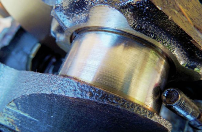 BEFORE
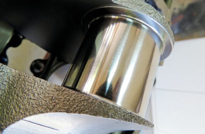 AFTER
AFTER
In the next installment, we’ll take these components and add them to the block along with the cam and pistons to assemble the long block.