Mike Lamz purchased a ’70 Chevy Monte Carlo four years ago. Initially equipped with a 350 small-block, an auto trans, and a 10-bolt open rearend, he swapped in a 425 hp, 454-HO big-block crate motor, a Muncie M20 (wide-ratio) four-speed manual trans, and a 12-bolt Posi rearend with 3.42:1 gears two years ago. The new 454 developed an internal vibration, requiring it to be rebalanced. While the motor was apart, it was refreshed with a hotter Comp Cams custom-ground hydraulic roller cam, roller rockers, and associated valvetrain parts. The existing factory rectangular-port iron heads were heavily decked to raise the compression ratio into the mid-10s. Despite the large head mill, Lamz’s Edelbrock RPM Air-Gap high-rise dual-plane intake bolted right up to the heads, initially sealing-up OK after being tightened to 25 lb-ft per Edelbrock’s instructions.
Over the next 1,000 miles, Lamz blew-out three sets of intake gaskets, always under compression-braking conditions: a sudden quick downshift into a lower gear at high engine rpm with a closed throttle. Severe compression braking can generate more than 20 in-Hg of vacuum, literally sucking the intake gaskets right into the ports. On the street, this occurs more often with a manual-trans car like Lamz’s than with an automatic, but we’ve also seen this syndrome in throttle-stop drag racing. The hefty Monte Carlo’s 4,200-pound weight doesn’t make things any easier.
“When this happened,” relates Lamz, “You could smell burning oil. It smoked like heck out the back of the car. That sucked.” And of course, it ran like crap until the gaskets were replaced -- with a massive vacuum leak, idle vacuum dropped through the floor.
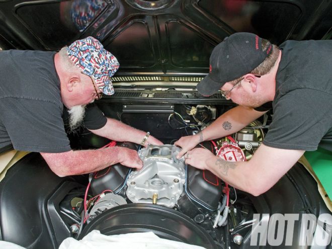
After three blow outs, Lamz knew it wasn’t a random problem, yet eyeball inspection of the gaskets revealed little evidence of distress. Time to bring in the specialists: Lamz hails from Genoa City, Wisconsin, not only right near rescue facility Westech Automotive, but also within spitting distance of Fel-Pro’s Chicago-area gasket factory, enabling Senior Fel-Pro Product Engineer Greg West to trek over to Westech and help scope out the issue. With Westech owner Norm Brandes and West combining their decades of experience, we knew Lamz’s Monte was in good hands.
 “Shhh. Be vewy, vewy quiet, I’m hunting a wascawwy intake weak.” Westech’s Ben “Elmer Fudd” Scully takes a bweak fwom wabbit-hunting to measure intake gasket crush uniformity using lead pellets from cut-open shotgun shells. Use No. 6 birdshot (nominally 0.110-inch diameter) with 0.050–0.070-inch-thick intake gaskets.
When the smoking wheezer arrived at Westech, idle vacuum was just 7–8 in-Hg. The engine kept running even after backing the throttle idle-speed screw all the way out -- a sure vacuum leak indicator. Spraying brake cleaner around the carb and intake manifold flanges and bolt-holes didn’t alter the idle speed, indicating no topside leaks. That left the valley side as the origin point, which Westech confirmed by spraying acetylene into the engine through holes in both valve covers; sure enough, idle speed increased. (You can shade-tree it with a propane bottle and hose.)
So much for what; the questions now were “how and why?” Combine all the different block, cylinder head, head gasket, and intakes out there with their varying machining tolerances, then add in block decking and milling (plus plain old machining errors), and it’s not uncommon to experience intake manifold sealing issues. Intake gasket failures most commonly occur due to any or all of the following conditions:
1. Warped intake manifold or cylinder head flanges.
2. Insufficient gap between the cylinder block and intake manifold front and rear sealing surfaces.
3. Bottomed-out intake manifold bolts.
4. Mismatched intake manifold and cylinder head ports.
5. Intake manifold sitting too high (or too low) in relation to the flange surfaces.
6. Fore-and-aft sealing flange out-of-parallel (the surfaces are flat, but they get wider or narrower compared to the opposite mating surfaces).
7. Incompatible intake and cylinder head flange angles (the surfaces check flat and are parallel, but the angles of each differ).
Brandes and his Westech crew went down the list to hone in on the failure cause.
1. Using a machinist’s straightedge and feeler gauges, they checked the manifold and cylinder head sealing surface, confirming they didn’t exceed the maximum allowable dimensions for a V8: no more than 0.004-inch out-of-flat end-to-end, or over 0.001 inch out-of-flat for any 3-inch diameter. Flanges exceeding these dimensions must be flat-milled straight.
2. The intake was installed without end seals. The front and rear gaps were checked and found to be within nominal parameters.
3. The intake manifold attaching bolts weren’t bottoming.
4. The intake and head ports were properly aligned, both with each other and the gaskets’ sealing beads.
5. Port alignment was OK. If alignment is off -- the intake sits too high or too low in relation to the port -- try a thinner (intake sits too high) or thicker (intake too low) gasket set, if one is available. Alternatively, mill the head or manifold flange if the intake ends up too high (often the case with decked blocks or heads).
This left possible Causes 6 and 7. Fel-Pro’s West points out that real world surface fore-and-aft out-of-parallel deviations and/or intake flange angle incompatibilities aren’t all that rare.
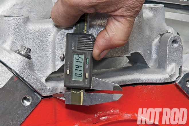 The front and rear intake-to-engine block “China Wall” gap clearance is often overlooked. If there is no gap or if the gap is too small, the manifold flanges will be held up off the cylinder heads. To check, bolt on the intake with side gaskets but without end seals. Measure the gap with feeler gauges or (as shown here on this demonstration engine) with a dial caliper.
Cork and rubber seals have a narrow tolerance for end-gap dimensional variations compared to silicone, so room-temperature-vulcanizing (RTV) silicone is preferred over old-school end seals on just about any engine except a straight restoration.
User-applied silicone beads are relatively forgiving, able to reliably seal 0.030–0.150-inch end gaps if allowed to properly “skin-over” for at least 10–15 minutes before bolting-on the mating part. RTV cures from the humidity in the air. Over 0.150-inch gaps require large, thick RTV beads, inhibiting proper internal bead air-curing that will, says Fel-Pro’s West, “turn the RTV material into mush” under prolonged usage conditions.
Cork or rubber seals must be compressed a set amount to seal effectively. Fel-Pro recommends the “30 percent” rule; that is, the end-seal gap should be 30 percent of the new cork or rubber end seal’s measured noncompressed thickness. For example, if using a 0.125-inch-thick gasket, the nominal end gap should be 0.0875 inch:
0.125 – (0.125 × 0.30) = 0.0875
Up to +5 percent deviation from this nominal value is usually OK, resulting in (for this example) an acceptable end-gap value of 0.83125–0.91875 inch. Obviously, that’s a much narrower tolerance than the RTV alternative.
If the end gaps are too small, mill the intake manifold front and rear sealing surfaces (or the equivalent surfaces on the block if it’s completely stripped down). If too large, some engine builders will make an aluminum shim and attach it to the engine block’s “China Wall” with at least three No. 10-32 countersunk screws. Finger-smear a thin silicone bead on the bottom of the shim, and place the main RTV bead (or gasket) on its topside.
The fix for bad angles, of course, is milling -- but at an angle needed to correct the problem, rather than just a parallel cut. However, there needs to be a way to detect the deviation in the first place and then determine the amount of correction needed to fix it. West’s practical solution: an extra set of intake gaskets plus 0.112-inch-od lead pellets. (Pros can buy pellets at industrial supply houses, but shotgun-shell pellets work OK, too.) As shown in the photos, drill small holes in the extra gaskets to accommodate the pellets. The amount of pellet compression when the manifold is tightened down indicates where and how much -- top-to-bottom, and/or end-to-end -- the machinist needs to angle-mill the intake.
On the Monte Carlo, the pellets compressed more at the port roofs than the floors. This dovetails with the valley-side gasket failures as well as the observed oil smoke coming out the tailpipes: Oil from the engine valley was being sucked into the intake ports. If anything, West says the gaskets should be compressed slightly more at the port floor compared to the roof to prevent this very problem. Info in hand, Brandes easily corrected the problem on the shop’s Bridgeport.
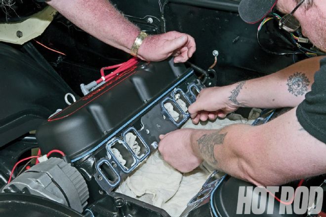
01 To check for uniform gasket compression, punch or drill holes near the port roof and floor (arrows) on each end of both gaskets (for a total of four holes/gasket). The holes must be large enough to accommodate the lead pellet after it’s compressed. A 0.200-inch hole is the right size for a 0.110–0.112-inch-diameter pellet.">BB’s don’t lie! We now have a more precise way to measure and machine an intake for best fit.
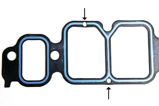 <strong>01</strong> To check for uniform gasket compression, punch or drill holes near the port roof and floor (arrows) on each end of both gaskets (for a total of four holes/gasket). The holes must be large enough to accommodate the lead pellet after it’s compressed. A 0.200-inch hole is the right size for a 0.110–0.112-inch-diameter pellet.
02 Use grease to hold the gaskets and pellets in place.">
<strong>01</strong> To check for uniform gasket compression, punch or drill holes near the port roof and floor (arrows) on each end of both gaskets (for a total of four holes/gasket). The holes must be large enough to accommodate the lead pellet after it’s compressed. A 0.200-inch hole is the right size for a 0.110–0.112-inch-diameter pellet.
02 Use grease to hold the gaskets and pellets in place.">
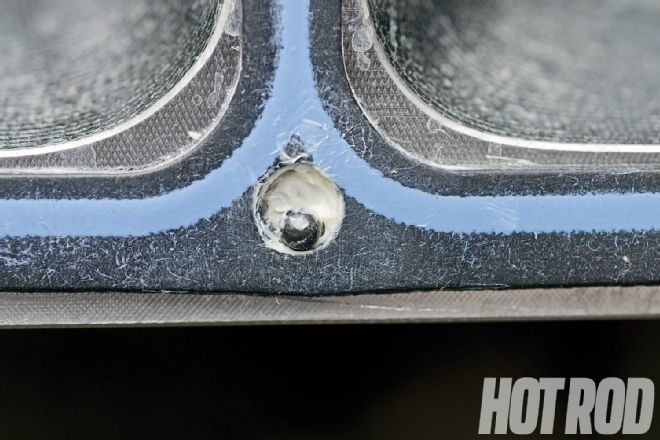 <strong>02</strong> Use grease to hold the gaskets and pellets in place.
03 Murphy’s Law! Just in case the pellets do fall out of place, put shop towels in the valley and cylinder head intake ports.">
<strong>02</strong> Use grease to hold the gaskets and pellets in place.
03 Murphy’s Law! Just in case the pellets do fall out of place, put shop towels in the valley and cylinder head intake ports.">
 <strong>03</strong> Murphy’s Law! Just in case the pellets do fall out of place, put shop towels in the valley and cylinder head intake ports.
04 Install the manifold without end seals, tightening it to the recommended torque value. This motor has cast-iron (not softer aluminum) heads plus (much) stronger-than-stock ARP intake bolts, allowing upping the bolt torque values from 25 to 30 lb-ft to provide a little more overall gasket compression.">
<strong>03</strong> Murphy’s Law! Just in case the pellets do fall out of place, put shop towels in the valley and cylinder head intake ports.
04 Install the manifold without end seals, tightening it to the recommended torque value. This motor has cast-iron (not softer aluminum) heads plus (much) stronger-than-stock ARP intake bolts, allowing upping the bolt torque values from 25 to 30 lb-ft to provide a little more overall gasket compression.">
 <strong>04</strong> Install the manifold without end seals, tightening it to the recommended torque value. This motor has cast-iron (not softer aluminum) heads plus (much) stronger-than-stock ARP intake bolts, allowing upping the bolt torque values from 25 to 30 lb-ft to provide a little more overall gasket compression.
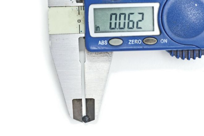
05 Remove the intake, taking care not to disturb the pellets. Label the pellets’ locations and their before/after compression thickness. A labeled ice-cube tray is one way to keep track of their location. The thickness of the pellets at each location establishes a guide to set up the manifold for machining.">
<strong>04</strong> Install the manifold without end seals, tightening it to the recommended torque value. This motor has cast-iron (not softer aluminum) heads plus (much) stronger-than-stock ARP intake bolts, allowing upping the bolt torque values from 25 to 30 lb-ft to provide a little more overall gasket compression.
05 Remove the intake, taking care not to disturb the pellets. Label the pellets’ locations and their before/after compression thickness. A labeled ice-cube tray is one way to keep track of their location. The thickness of the pellets at each location establishes a guide to set up the manifold for machining.">
 <strong>05</strong> Remove the intake, taking care not to disturb the pellets. Label the pellets’ locations and their before/after compression thickness. A labeled ice-cube tray is one way to keep track of their location. The thickness of the pellets at each location establishes a guide to set up the manifold for machining.
06 In the Monte’s case, the 0.112-inch-diameter pellets were compressed more (ended up thinner) at the port roof than at the floor. This is the proximate cause of the gasket-seal failures.">
<strong>05</strong> Remove the intake, taking care not to disturb the pellets. Label the pellets’ locations and their before/after compression thickness. A labeled ice-cube tray is one way to keep track of their location. The thickness of the pellets at each location establishes a guide to set up the manifold for machining.
06 In the Monte’s case, the 0.112-inch-diameter pellets were compressed more (ended up thinner) at the port roof than at the floor. This is the proximate cause of the gasket-seal failures.">
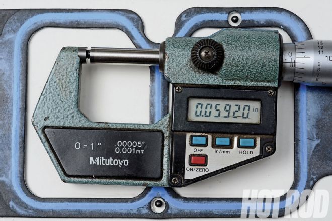 <strong>06</strong> In the Monte’s case, the 0.112-inch-diameter pellets were compressed more (ended up thinner) at the port roof than at the floor. This is the proximate cause of the gasket-seal failures.
No brain surgery here: Get the right angle, and you’ll save the seals. “Everything’s fine,” sums up a satisfied Lamz. “I haven’t had any problems since!”
Compression braking can unhinge a marginally sealing intake manifold, even if things initially seem OK on the dyno. Consider checking the intake-to-head sealing parameters and angles as standard operating procedure for any serious performance engine buildup, particularly with a heavily milled block and heads.
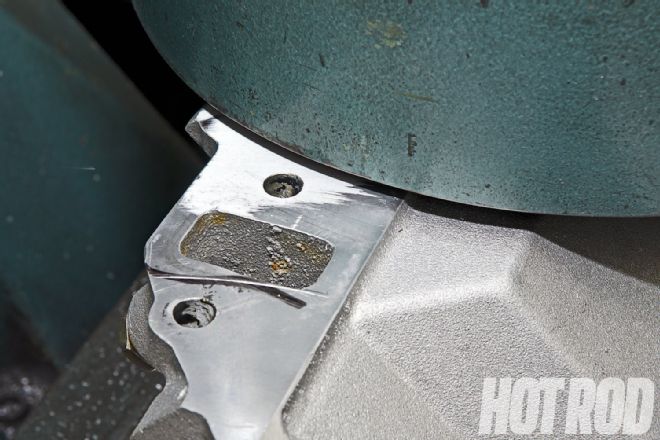 After completing the angle mill, slight distortion remained near the front water passage (note nonshiny, nonmachined area, a sign that this area remains lower than the flange). Flat-milling another 0.003 inch off the surface as a whole cleaned it up. The intake was flipped to the passenger-flange side, again dial-indicated, and the milling process repeated.
The valley side (port floor) of the flange should have the same to as much as 0.003-inch greater gasket compression than the roof. In the Monte Carlo’s case, the pellets at the roof were compressed to 0.059 inch, but were only squeezed to 0.062 inch at the floor. Pellet compression at the floor would need to be squeezed down another 0.003–0.006 inch to compress them to 0.056–0.059-inch.
After receiving this data, Westech set up the intake in the mill. First, the machinist “zeroes” the flange’s floor-side during setup, then rotates the manifold so the roof side is 0.003–0.006-inch higher in the mill than the floor side. The cut is made incrementally in several passes to confirm the manifold’s overall straightness while checking for any localized distortion. If any additional cleanup is required, and/or there was front/rear deviation, the intake needs additional material removal. The same process is repeated for the opposite flange. The total material removal amount from each side is based on the side that is furthest off (requiring the deepest cut) to ensure the intake remains centered on the engine.
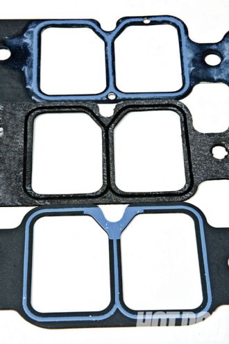 The Monte Carlo’s intake gaskets, from top: Fel-Pro PN 1211 composite gasket, used for mock-up (note added pellet holes); original leaky Brand-X gasket (note small sealing bead); and highest durability, Fel-Pro steel-core laminate PN 1211 S-3 used on final assembly. The latter’s slightly greater thickness also helps compensate for the material milled off the intake’s flanges.
The GM rectangle-port iron heads on the Monte Carlo’s 454 engine still have upper bolt-holes between each intake port pair. Lamz also didn’t need exhaust heat in his application. Fel-Pro offers at least two high-performance intake gaskets that fit the heads with these desired characteristics. Both have Printoseal beads around the ports for added sealing ability.
Steel-core intakes are more durable for long-term street use. According to Fel-Pro’s West, “We have also found a benefit to using the steel-core intakes on engines used in NHRA Super Comp, Super Gas, and Super Street classes, and on some circle-track engines. In those classes where throttle-stops and timers are used, leaving the starting line hard on the throttle, slamming the throttle shut for a given amount of time, then getting back on the throttle hard can suck a composite gasket into the intake port. The same applies to circle-track apps where the driver is using the throttle like an On/Off switch. The downside to steel-core gaskets is that they are difficult to trim. The nonsteel-core gaskets like PN 1211 are easily trimmed to fit the heads and manifold, and they are more conformable than a steel-core gasket.”
Need Junk Fixed?
If your car has a gremlin that just won’t quit, you could be chosen for Hot Rod to the Rescue. Email us at [email protected] and put “Rescue” in the subject line. Include a description of your problem, your location, and a daytime phone number.
Contacts
Fel-Pro Federal Mogul; Southfield, MI; 800.325.8886 or 248.354.7700; FME-cat.com/digipubZ/Felpro-Performance-Gaskets
Summit Racing Equipment; Akron, OH; 800.230.3030 (orders) or 330.630.0240 (tech); SummitRacing.com
Westech Automotive; Silver Lake, WI; 262.889.4346; WestechAuto.com