Finding 100 horses in a Tri-Power 421
Last month HPP introduced to the readers a ’64 421 H.O. Tri-Power engine buildup being performed by Jim Taylor. The goal of the project is to try and find 100 additional horsepower in a cast-iron cylinder head (casting #716), iron intake manifold, and small intake-valve (1.92 inches) Pontiac. A lofty goal when one considers the small throat area of the #716 cylinder head. To further complicate the task, Jim insists the engine employs Pontiac induction parts from the carburetor air horn to the intake port of the cylinder head, albeit maybe not all from ’64. He had some levers to pull to accomplish his self-imposed goal, so a brief review would be in order.
Recognizing that there are many factors involved to convert chemical to mechanical energy with an internal combustion engine, Jim’s approach was multi-faceted. Every engine suffers from three areas of loss. A loss in engineering parlance is described as something that does not allow the full chemical energy potential from the fuel to be transferred to the crankshaft. These areas are identified as pumping, thermal, and frictional losses.
A pumping loss is the amount of work the engine must perform to fill the cylinders with a charge and then exhaust the spent gasses. Traditional modifications to the intake and exhaust path, such as better flowing components and headers are an example of minimizing pumping losses. The 421 build addressed this with flow bench testing of the cylinder head and Tri-Power manifold with the three Rochester carburetors attached.
Thermal losses can be addressed in many ways with the most effective being an increase in the static compression ratio of the engine. The compression ratio is a result of the change in volume of the bore with the piston at bottom dead center and then at top dead center. In any engine an increase in compression ratio will provide a lock-step improvement in thermal efficiency. Thermal losses are the energy that goes into the coolant and out the exhaust pipe instead of working against the piston.
Jim looked to keep thermal loss at bay and still maintain the engine’s street nature. He accomplished this by pushing the envelope for compression ratio to 10.6:1 and tricking the combustion event to bleed off some of the cylinder pressure at light load with modified cam timing. This would make the Pontiac less octane sensitive.
The dyno test will be run using VP C-9 that is rated with the following specifications:
Frictional losses are the energy consumed by the actual mechanical operation of the engine. These are the turning of the crankshaft and camshaft, the movement of the valves, and the operation of the oil and water pumps. When an engine operates, friction is produced and any efforts taken to minimize it will show up on the dyno needle. Thus, the 421 employed light-weight pistons and rods along with a mechanical advantage created by the valvetrain geometry and modifications to the oiling system to limit oil whip during running.
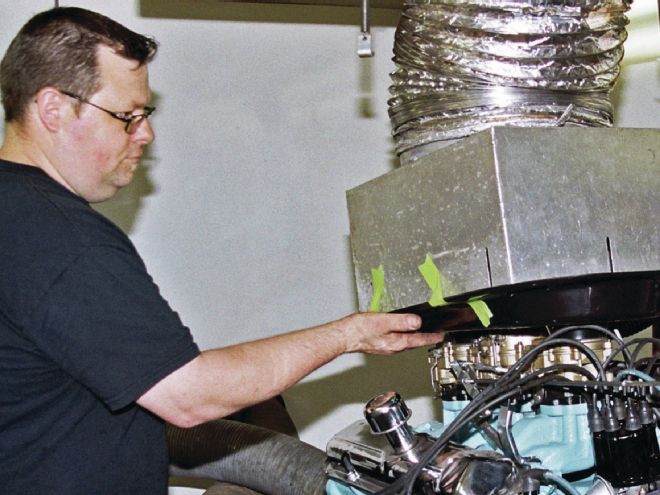
14. Once at Bitner Automotive, Mark Erney was responsible for connecting the 421 to the dyno. The engine employed 1.75-inch headers with three-inch collectors and one thermocouple on each cylinder bank. ">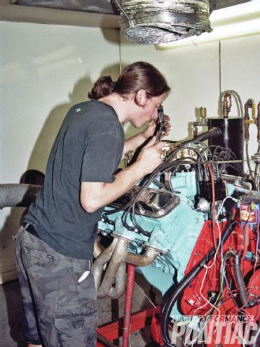 <strong>14.</strong> Once at Bitner Automotive, Mark Erney was responsible for connecting the 421 to the dyno. The engine employed 1.75-inch headers with three-inch collectors and one thermocouple on each cylinder bank.
As an aside to this, in ’63 Pontiac issued a service bulletin to all dealers requiring a new dipstick to be installed in the 421 H.O. engines. What was discovered is that under hard braking as would be experienced after a run at a dragstrip the oil would move forward and away from the pick-up, temporarily starving the lubrication system. The new dipstick was marked so that when it read full, the pan would now have six quarts of oil instead of the normal five quarts. This simple change cured the issue that would not be seen during normal driving.
15. With the engine nearly ready for its break-in, Mark Bitner, Jim Taylor, and Mark Erney give everything a look over one last time. ">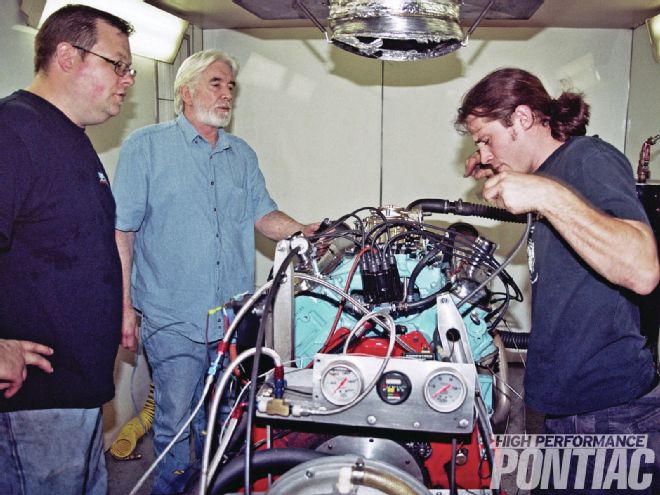 <strong>15.</strong> With the engine nearly ready for its break-in, Mark Bitner, Jim Taylor, and Mark Erney give everything a look over one last time.
Now keep in mind that Jim’s self-imposed restriction of employing mostly factory parts made the task of eradicating the three areas of loss much more difficult. For example, the major stumbling block would be the small intake valve size that must be used with the #716 cylinder heads. This is due to the combustion chamber design.
Also, wanting this exercise to mimic what Pontiac could have potentially done when this stellar engine was in actual production, Jim insisted on still using the Delco breaker-point distributor with no electronic conversion.
16. Fred Bitner awaits their OK to take the controls of the dyno. The Pontiac fired right up and he spent a good deal of time making break-in pulls to seat the rings before we went for the power.">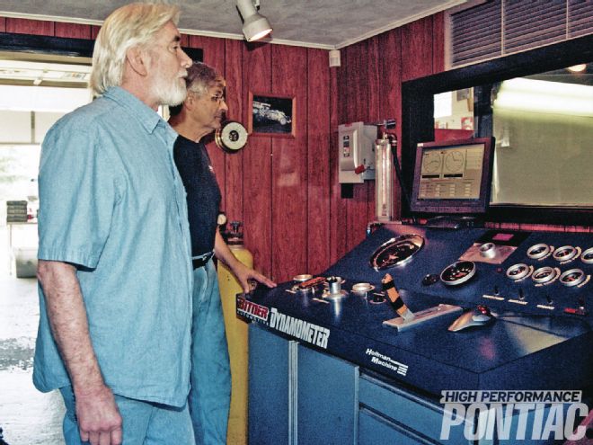 <strong>16.</strong> Fred Bitner awaits their OK to take the controls of the dyno. The Pontiac fired right up and he spent a good deal of time making break-in pulls to seat the rings before we went for the power.
In many ways, he tied his own hands, but for the dream to be fulfilled, the clock needed to be turned back to the mid-’60s and stay there. The 421 would be era-correct even though it is now 2013.
So get comfortable and follow along as we bring you to that faithful day when the 421 challenged the water brake at Bitner Automotive in Trenton, New Jersey. Let us see if Jim meets his goal and makes his dream come true.
Nowadays only 2 in 10 outer carbs I get in for rebuilding still have the diffusers in them
HPP Engine Buildup Worksheet
Bottom End
Oiling System
Heads
Cam
Induction
Ignition
Exhaust
Gaskets
It Only Takes Two!
When first exposed to the thought of testing a Tri-Power equipped Pontiac with the two outboard carburetors disconnected, the knee-jerk reaction is probably, why?
Jim Taylor’s reasoning behind this final test we did that day was to assign a hard number to the kick one feels when matting the throttle and allowing for the improved volumetric efficiency that the other two Rochester carburetors bring to the game. Well, with this engine that number is approximately 123 hp. The 421 made a hair shy of 350 hp when running on the center two barrel alone. Jim finally got his answer to a question he has been asking himself for decades.
As the author, this test not only satisfied Jim’s curiosity but also proved something I believe more valuable—it debunked the age-old myth that a Tri-Power manifold would offer poor fuel distribution during street driving.
For as long as I can remember, it was believed stunning performance and good drivability were not achievable with three carburetors. If that was the case then the engine would not have made 350 hp on the dyno with excellent loading and good fuel distribution. The only caveat being that the carburetors need to be set up properly, and Jim certainly knows how to do that.
The moral of the story is if you have a Tri-Power Pontiac that suffers from poor light-load performance, stop blaming the manifold design. When they are right, they are right, and when they are wrong—well, you know the result!
Dyno Results Power with only the center two-barrel operational