Being in the business of building classic trucks, if you ask me which is better, a straight axle with power steering or an independent front suspension, I'm going to recommend IFS every time. In my opinion the money spent on an IFS installation is some of the best money you can throw at a truck. I have had several customers who swore by the dropped axle with all the brake and steering upgrades as they were building the truck. Once they started driving it their story changed. Most ended up giving into the independent route. I think it really comes down to how much you're going to drive the truck. Any daily driver I'm putting together is going to have an independent frontend just for drivability. A casual weekend driver could probably put up with the straight axle and the way they drive.
With the 1953-56 Ford trucks, one of the best steering boxes to use, if you gotta have the straight axle, is the power steering box from the 1980-87 Toyota four-wheel-drive pickups. There are two different types available and the one we're using here has four symmetrically square boltholes to mount it. The other model that you don't want is the one with three mounting holes. There is even a manual four-hole steering box from that same Toyota 4x4 that will also work and is an improvement over the stock Ford box, but if you are going to all this trouble in the first place, the power box is the only way to go.
Although the manual box wouldn't need a pump, Mid Fifty suggests that you also get the big nut for the sector shaft as well if you score yours from a local wrecking yard. They will even buy the stock Toyota pitman arm from you for $10. They use them to make the new one used in the kits. There isn't any heating or bending of the arm. They simply drill out the hole for the drag link and TIG weld in a newly machined ball end to accept the stock Ford drag link.
All of the parts to install the Toyota steering box, the power steering hose kit, and tilt steering column came from Mid Fifty F-100 Parts. Some of the parts used in the kit are from Classic Performance Products. Mid Fifty simply puts together everything needed. The only thing that wasn't included in this kit was the power steering pump and mount. Pretty much any pump that is commonly run will work just fine with the Toyota box. I chose a GM canister pump from the early 1970s since it is easy to mount, cheap, and readily available. The power steering hose kit is a CPP kit also. The hoses are very good quality and should last for years.
There is a difference in the size of the return fitting between years. The early boxes from 1979-80 had a return port size of 14mm x 1.5mm. The steering input shaft is different in the 1979-80 boxes, in that the shaft and splines are straight. There is no machined area on the shaft where a locking bolt or pin could reside. The 1980-85 steering boxes, however, have that machined slot on the input shaft and the return port is now 17mm x 1.5mm.
So rather than have the tech phone ringing off the hook over at CPP, they just included the five possible fittings you might need in the kit. The kit includes five male to male fittings: (1) 14mm, (2) 16mm, (1) 17mm, and (1) 18mm.
The swap was pretty easy and straightforward. The disassembly was dirty and nasty, but hey, if you don't get dirty they won't believe you did anything. In this installation, with the small-block Ford that had been previously mounted, there weren't any clearance problems. The Toyota box cleared the engine and the exhaust. Everything bolted right up like it should and made for a nice installation. The only thing I found on my installation was the stock sector shaft hole in the framerail that the instructions said to open up 1⁄8-inch and I found it needed 3⁄8-inch. Other than that it installed like a dream.
The steering column was next and it also was a snap. I bolted the 4½-inch Flaming River steering column drop to the underside of the dash. When I test-fit the CPP steering U-joint onto the shaft of the steering column I saw the shaft needed to be shortened some and the shift lever arm should be changed to the offset one CPP includes in the steering column box. The pictures and text will detail this.
With the steering box and column mounted it's time for the real fun part, which I'll show ya next issue in part 2 of this install where I'll be making the bracket for the power steering pump and installing the hoses, so stay tuned. See ya next month.
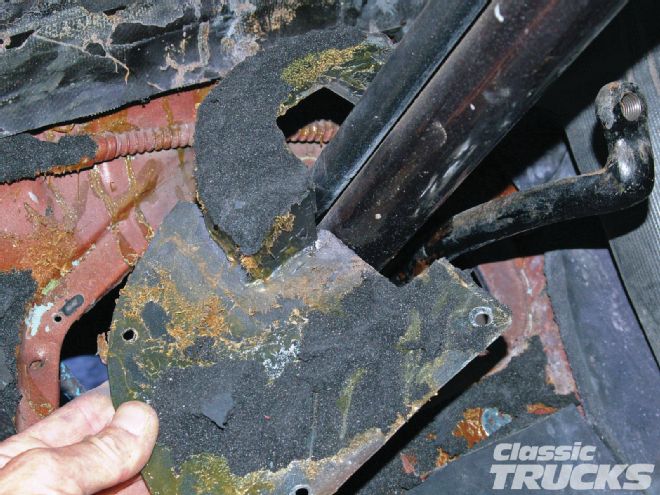 01. First I loosened the bolts for the steering column mount at the dash. Remove one and leave the other one loose. Then remove the floor fill from around the base of the steering column. I'll be bringing the old steering box up through this hole to remove it. The shifter also gets disconnected, as does the turn signal wiring. Marking the wires as to what they do before ripping them out is always a good idea. It will help when connecting the GM tilt column's turn signals.
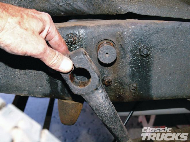 02. Next is the pitman arm from the steering shaft. Remove the bolt and nut first then the arm just slides off the shaft. Then remove the three bolts that mount the steering box to the framerail.
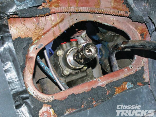
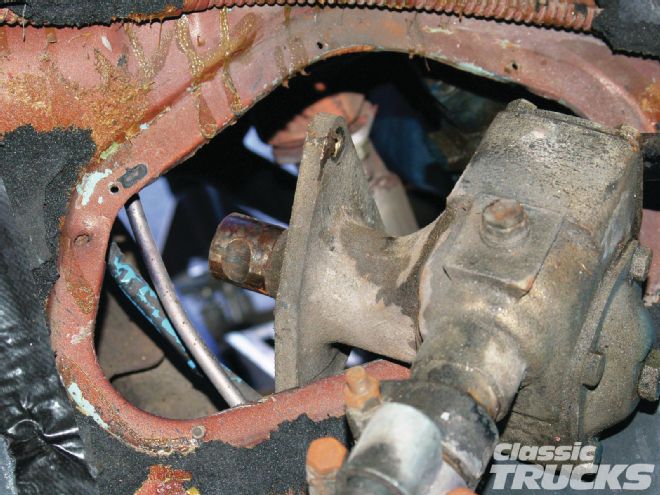 03. Now from back up in the cab, remove the loose bolt on the steering column mount and grab a hold of the steering column. First I work it out of the framerail, then up through the hole in the floor. The whole steering column/box assembly will come right out. You will have to rotate it around as you come through the floor opening.
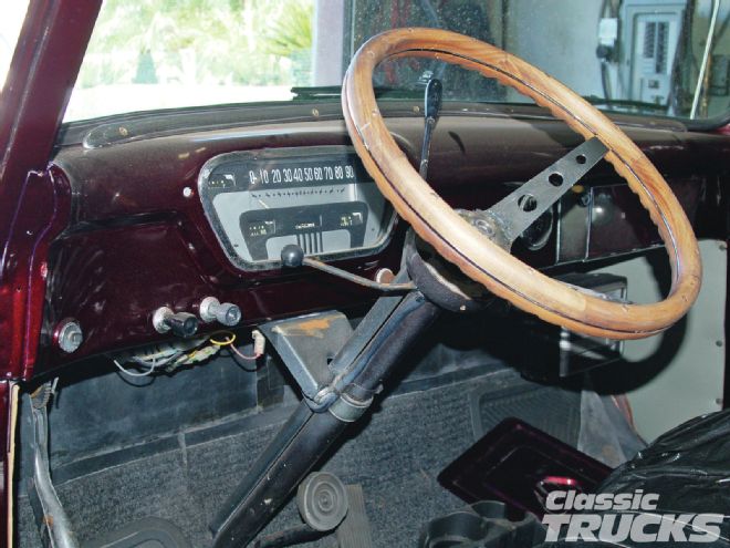
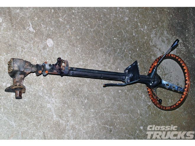 04. This column has seen better days and the steering box is junk. It felt like the sector shaft was skipping inside. Amazingly it was driven into the shop. The guy said it was a hairy ride. There are such better options available nowadays that nobody, except the resto crowd, should be using these old boxes.
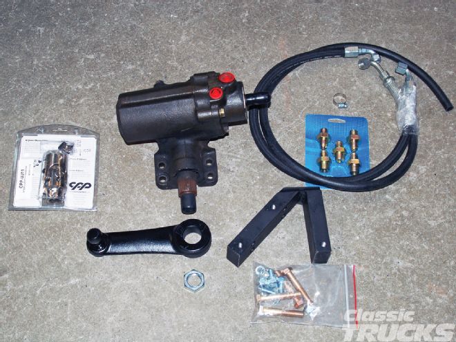 05. Here's the Toyota power steering swap kit. Everything needed to install the box and the hose kit. There is a difference in the return line fitting size during the run of those steering boxes so Classic Performance Products has included any of the ones that might be needed in the fitting kit. The hoses were plenty long enough to connect to the pump.
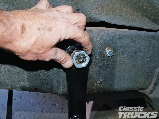
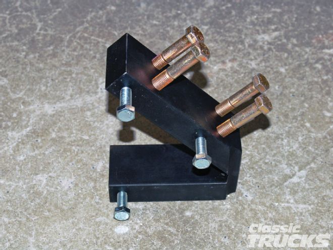 06. Here is the mount that will bolt to the steering box with the four gold-colored bolts and to the frame in the stock holes with the silver-colored bolts.
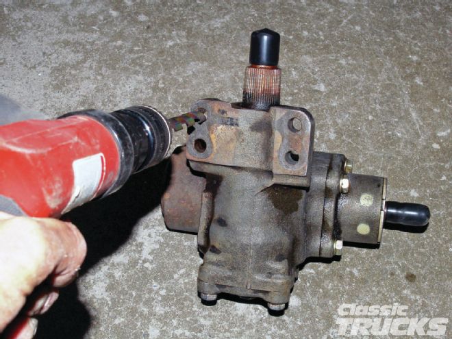 07. The bolts didn't want to fit right into the holes in the steering box so I ran a 7⁄16-inch drill bit through the mounting holes to clean up the holes. A hole for a metric bolt is always a little smaller than it is for a standard one.
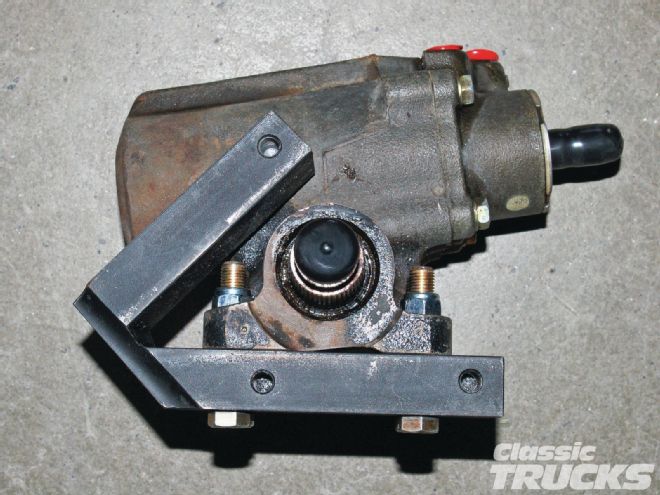 08. The instructions say to mount the steering box to the mount and then install into the framerail. That sounded like the best way to me too, so I bolted it to the mount and was ready to test fit.
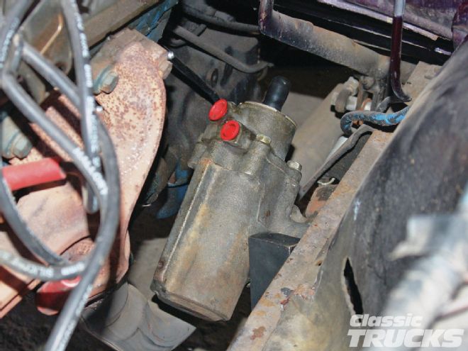 09. With this little small-block Ford there wasn't any obstructions and I ended up with nice clearance around everything when the box mount was tightened down. I brought the box up from the bottom to install it, but it could have come down from the top as well.
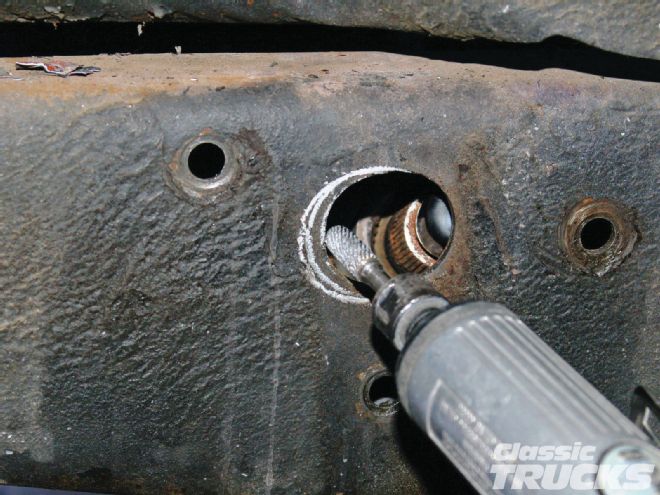 10. The instructions said the stock hole for the sector shaft would have to be opened up 1⁄8-inch or so, on the forward part of the hole. I found after a few test fits that 3⁄8-inch worked better for me. A high-speed grinder with a carbide cutting bit made short work of opening up the hole as needed.
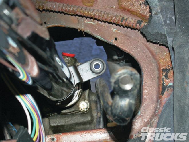
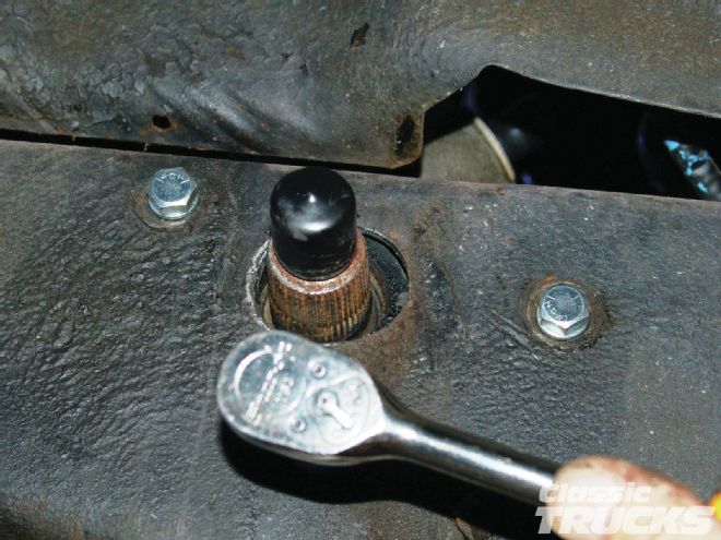 11. From underneath, lift the box in place and line the holes up and install the mount bolts. I found after running the engine to bleed the power steering lines that these bolts needed to be impacted down. Be careful as they are just 3⁄8-inch bolts, but they do need to be real tight so the steering box doesn't move when you turn the steering wheel. I didn't get them tight enough with just the ratchet. Also shown here is the clearance around the sector shaft. Opening it up a little bit more gave plenty of clearance around the casting of the sector shaft.
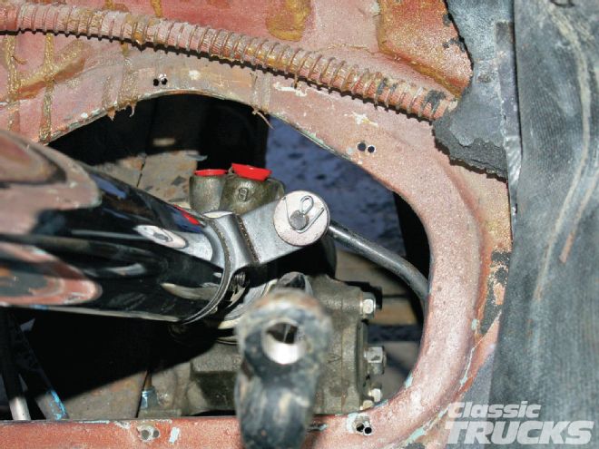
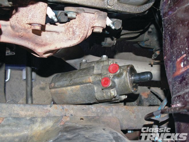 12. With the steering box mount bolted in, these pics show how well the steering box clears the engine, framerail, and floor of the cab. Exhaust clearance is pretty good and you could probably get a set of shorty headers to work.
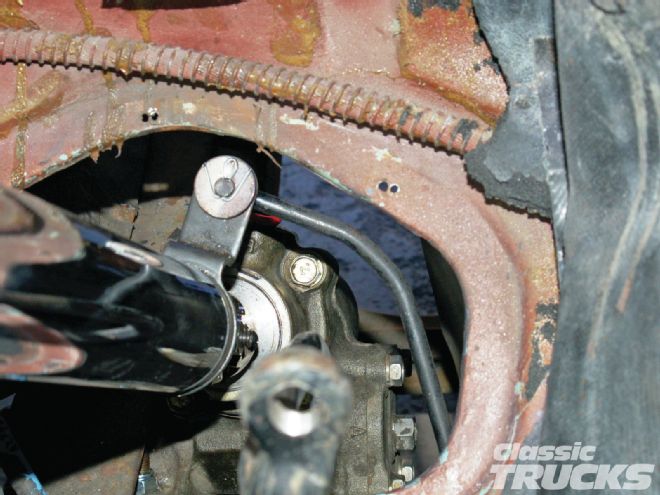
 13. As you install the supplied Toyota pitman arm, you should make sure the steering box is at its center location. I put the new steering U-joint on the input shaft and turned it all the way one way. Then turn back counting the turns. This was just over four turns. I turned it back just over two turns and, with the front wheels straight, connected the pitman arm to the sector shaft. They are both splined and it fit right together. The new nut was also installed and tightened.
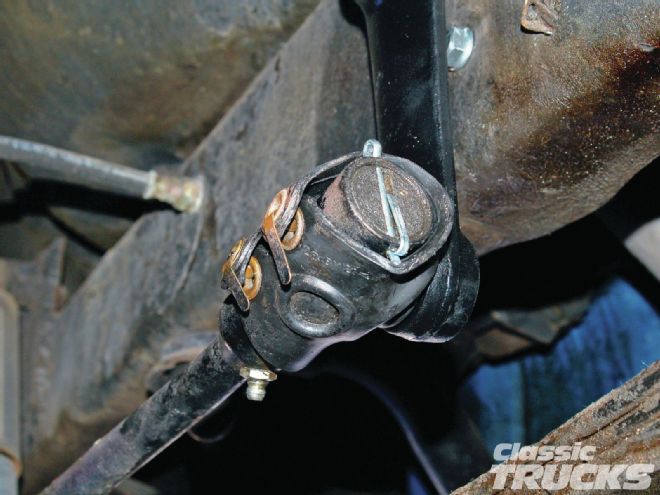
 14. To remove the stock pitman arm from the drag link, first remove the cotter pin
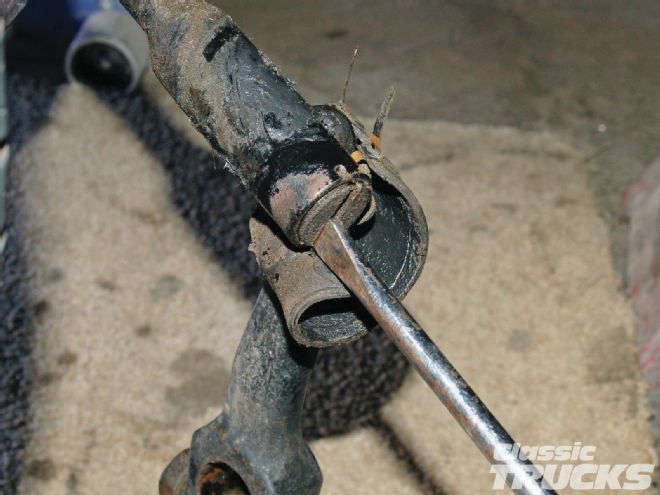 15. Then unscrew the plug with a large flat-blade screwdriver. You don't have to take it all the way out, just until the ball of the pitman arm will fall out.
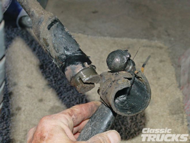
 16. Installation of the Toyota arm is just the reverse. Insert the ball into the drag link and tighten the end plug. Install a new cotter pin and you're done. This truck had the stock grease cover that was in great shape so I cleaned it up and reinstalled it on the new pitman arm.
 17. That pretty much completes the steering box installation. With the new steering U-joint on the box it's time to move on to installing the new CPP tilt steering column. I will get the column bolted in place and make a new fill piece to fit around the steering column.
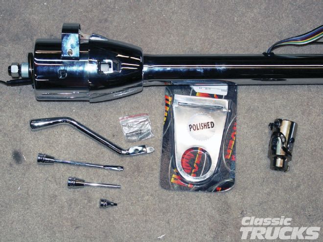 18. The steering column portion of this kit contains a new Classic Performance Products GM style, polished tilt steering column, a Flaming River 41⁄2-inch column drop and the required steering U-joint, also a CPP product. You also get a cool shifter arm, turn signal, and tilt levers. Two different lower shift arms and an OD indicator if you happen to be using an OD trans. Turn signals are GM color-coded.
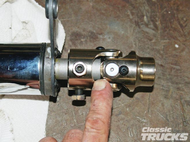 19. I slipped the U-joint onto the steering column shaft mainly to make sure it fit. A lot of times you need to do a little file work on the inside of the U-joint or the shaft. These went right together, but I noticed that there was an extra 5⁄8-inch of shaft. I knew clearance was going to be tight and I wanted the U-joint right up at the screws for the shift arm. I marked the shaft and cut off the excess with a cut-off wheel.
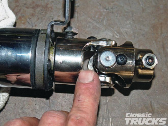 20. After the cut, the steering shaft now ends in the proper spot. If too much shaft sticks through it can jam on the other side as it is turned. This is more noticeable if the U-joint is working at an angle. This one is pretty straight into the steering box, but I still didn't want to take any chances.
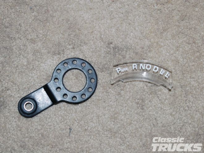 21. CPP also provides an offset shift arm and an indicator for an overdrive trans-equipped application.
 22. I changed to the offset shift arm because I was pretty sure it was going to be needed to clear the cab floor.
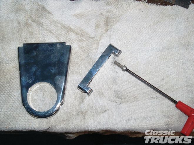 23. Here's a pet peeve of mine. If you are going to sell me something cool that requires a certain kind of bolt to mount it, please supply those bolts too. This column drop needs two 1⁄4x1-inch socket head bolts to fit into the machined mounting holes. Luckily I had a couple on hand, but not everybody does. After I found the needed bolts, I bolted the column drop to the bottom of the dash.
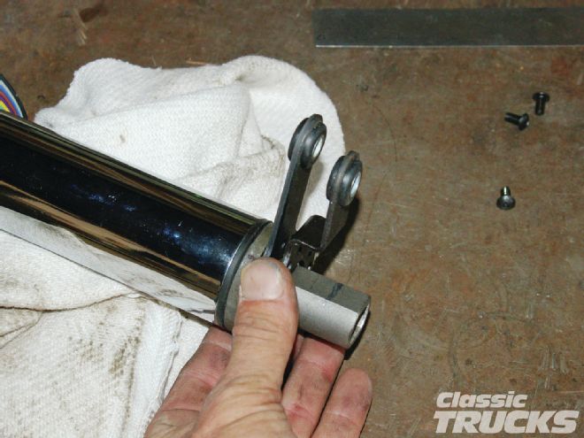
 24. This was the only problem I ran into with this whole installation. The shift arm was going to be right in the way of the brake pedal when it was in drive. Since the bottom of the column has threaded holes all around, I took the arm back off and remounted it with another hole to the driver side. This moved the arm to the left more and I was even able to get low gear and not be in the way of the brake pedal. Re-bending of the shift rod got everything working in harmony.
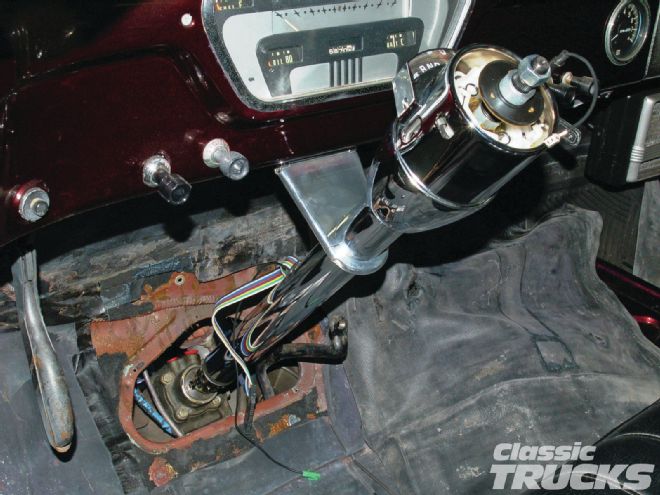 25. Looking good so far. What an improvement over the stock steering column. Next I'll make a fill piece to fill that hole in the floor and wrap around the steering column.
 26. I knew I was going to need that offset shift arm. But with it installed there's all kinds of clearance. This is really making for a nice installation.
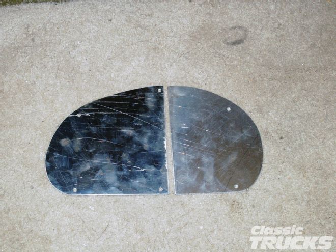
27. Since I have had to make hundreds of these over the years, I have a good pattern that I start with. I chose aluminum to make the fill piece out of, but steel could be used as well. Aluminum is just so much easier to work with.
26. I knew I was going to need that offset shift arm. But with it installed there's all kinds of clearance. This is really making for a nice installation.
27. Since I have had to make hundreds of these over the years, I have a good pattern that I start with. I chose aluminum to make the fill piece out of, but steel could be used as well. Aluminum is just so much easier to work with.
 28. Starting with the easy side, I eyeball the center of the steering column and make a mark on the aluminum. Using the mounting screw holes in the floor as a reference, I figure out how deep the cut needs to be to fit the column. Then using a 2-inch circle gauge I mark the radius to be cut.
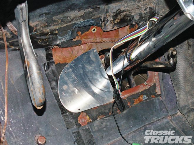
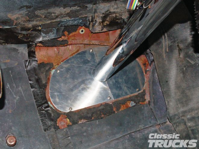 29. After cutting it out on the bandsaw it usually takes a little filing and it will fit the column nicely. Same was done to the other side. I have removed the brake pedal bolt to let the pedal drop down out of the way. Now that the fill pieces fit, I crawl underneath and hold the pedal up to the aluminum and mark the required hole using the pedal as a guide. You want the hole just big enough that the pedal arm will pass through as the pedal is depressed. I have had to remove quite a few pedal arms and straighten them out so they would work, otherwise the hole would have been huge.
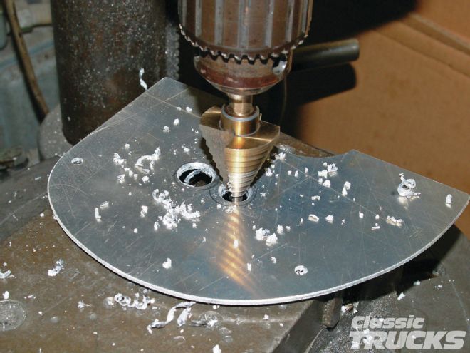 30. Once again I use a circle template to lay out two 7⁄8-inch holes, one right on top of the other. My step drill bit is awesome at opening up the holes. Sure beats fighting a big 7⁄8-inch drill bit.
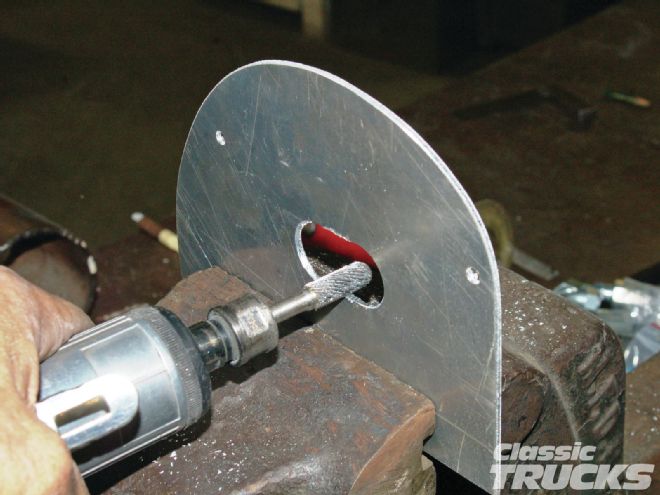 31. A couple of quick passes with a die grinder and a carbide bit and the slot for the pedal is taking shape.
 32. The shifter before re-clocking it.
 33. By re-clocking the shifter arm on the bottom of the column and moving it up, I was able to reshape the shift rod and have everything work and clear the brake pedal as it is depressed.
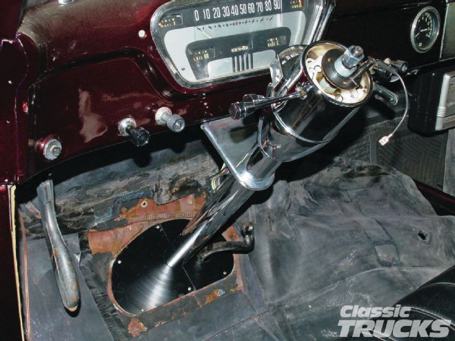 34. The finished installation. Turn signal wiring has been connected and the shift lever, turn signal, tilt levers, and the hazard button have all been installed as well. Customer just needs to decide on a steering wheel and he'll be cruisin'! In part 2 of this install I'll make the mount for the power steering pump, and install it and the hoses. See next month!