Here it is, just like we promised. This second installment of Mike's LS swap picks up right where we left off last month with the location and mounting of the fuse panel and fuel pump relay and onward through the balance of this informative engine swap.
The harness has a fuse panel and fuel pump relay that need to be mounted. The fuel pump relay will go in the passenger side kick panel area and the fuse panel will go on the 1x1 square tubes within reach if needed. The harness also includes a connector for the diagnostic connector; it will go in the glovebox. This is where you hook up a code reader to find trouble codes that have been set if there is a problem. A check-engine light lead is also provided and I will install one over by the computers.
Fuel System
Switching to a fuel-injected engine will require an upgrade of the fuel system. The fuel pump needs to be electric and mounted in the tank for best results and longevity. The frame-mounted fuel pumps just don't seem to last with the rigors of daily driving.
Most EFI systems use a feed and return line. The feed line comes from the pump, through a filter, and goes to the inlet on the fuel rail. The return comes from the fuel-pressure regulator of the rails and goes back to the tank. Around 1998-99, they switched to a single feed line. GM has the return line at the filter now and Ford uses a check valve in the pump itself with no return line. Mark sent along a fuel filter kit with a Corvette filter and the required fittings with -6 connections.
I like doing all the needed fuel lines in 3⁄8-inch or -6 if using stainless. I use -6 stainless flex hose to connect the tank to the steel lines, and the feed line to the fuel rail.
Choice of fuel tank is up to you and stock ones can even be modified with an electric pump setup by someone familiar with what's required. There are many fuel tank fabricators out there that make some really nice tanks these days, covering many applications. We're using a new stainless tank with the pump installed and the ports provided for the feed and return. This beauty comes from Rick's Hot Rod Shop. He builds awesome stainless tanks for Ford, GM, and Chrysler muscle cars and hot rods. Ricks tanks are carried by Jegs, Summit, Classic Industries, and Year One to name a few. Tanks can be ordered direct and custom tanks are also available.
With the tank mounted, I can figure where I want the hardline to start from and run to. From that point I bend up some welding wire to the shape and fit I want from the steel line. It will run to where the fuel filter is mounted. I bend up the hardline and install it with the clamps to hold it to the framerail. Then I bend up more wire running the steel line up to the engine area. Next is the return line, figured the same way with the welding wire. You certainly could hook the hardline right to the tank; I find that a flexible connection makes removing the tank in the future an easier process in most cases.
The fittings on the fuel filter and the feed line to the rails have -6 fittings, so even though I'm running regular steel line, I'll still use the -6 AN nuts and sleeves on the lines. I just give the steel lines the same single style flare the AN's use. The fuel tank has 3⁄8-inch pipe ports so I'll get a couple of 3⁄8x-6 fittings for that, the three steel lines used will need -6 nuts and sleeves, three unions to connect the flex lines, and the flex line fittings, two -6 straight and two -6 90's. The 90's will go to the tank.
The hard line I use is 3⁄8x60-inch steel fuel line from the parts store. These two lines made it up the frame and were joined with two shorter pieces to get to the filter that was mounted up just behind the battery on the inside of the framerail. You want to find a spot that is easily accessed so you can replace it when needed.
The back of the filter has the two lines, the front toward the engine has one. Of the two, the bottom one is the feed and the middle one is the return. The hardlines are bent up and connected to the filter keeping with this relation.
Street and Performance has a flex feed line that connects the stock fuel rails and runs down behind the engine and down to the passenger framerail. Where it ends determines where the hardline will end. I make up the short piece of hardline from the filter to a -6 bulkhead fitting and clamp the line in place, and then connect the feed line.
The flex lines at the tank are made up and fit and since this panel truck has a raised floor, I'm not limited in how the lines can run. The fuel sender has been swapped over to the new tank; it and the pump have been wired, so the fuel system is done.
Exhaust System
We ran into a problem with the headers on this installation because of the aftermarket crossmember's design. Those that are running a Mustang II or Flat Out Engineering's Corvette crossmember shouldn't have much of a problem finding headers. The only point of interference is the steering shaft and driver side header. Some repositioning of the bottom of the steering column will help. Don't be afraid to move the bottom of the column out, away from the engine somewhat to give the steering shaft a bit more length, and in turn, clearance at the header. Another trick is using three steering U-joints and a support bearing for the shaft and you can snake the shaft around anything.
This exhaust system was done by Street Rod Mufflers in Corona. Since headers had to be made, the best set by far are long tubes. The set we got is just beautiful. They made and ran the whole system all the way back, then had it all Jet Hot coated. This was money well spent. A great set of tubes that will give us 15-plus horsepower over stock manifolds and the complete system coated and installed. By getting the exhaust system done and out of the way now, as I wire the engine I will know where to steer clear of the exhaust when routing the sensor wiring to the lower part of the engine and the O2 sensors. Plus when it's all wired, we can fire it up and see how she runs.
Radiator and Cooling System
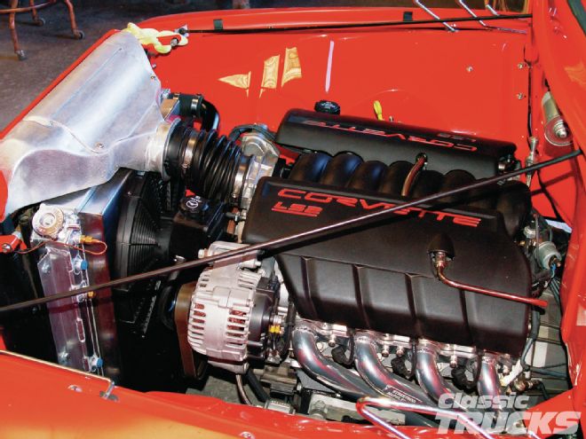
We're using an aluminum crossflow radiator that actually came from Mid Fifty F-100 Parts. They have always had the stock-style replacement radiators, but Sy figured with the popularity of the crossflows in the trucks, she should offer a few versions. I have also done these swaps with a '56-style radiator. Both work great. The key is to always run a fan shroud and the biggest fan that will fit. The reason this one has the crossflow is the cold-air induction/filter box that was made to fit above the radiator. This took care of the sharp turn the intake would need to clear if you ran a filter off to the side as required with a tall stock radiator. The LS's mass air meter fits into the opening and makes for a nice intake solution.
The next problem we run into is the radiator hoses. It's a pretty close fit for the upper hose and the lower needs to make a couple of tricky bends to connect. Rubber ones probably could be found, but the fabricator in me wants to make something a little better looking.
The upper hose is 11⁄2-inch and the lower is 1¾, so I get a few steel U-bends in those sizes and start making up some steel "hoses." To connect them I'll use short pieces of rubber hose and some clamps. You can go a step further and use the polished aluminum sleeve-type ends that come with the stainless flex radiator hose kits that are out there. Summit has just the end covers available. Paint the steel hoses body or engine color and the aluminum ends really dress up the hose. I have even hidden sensors in the bottom of the upper hose by welding on pipe-tapped bungs. The LS block doesn't have any extra water or oil ports for senders.
The LS kind of changes it up and puts the thermostat at the lower hose. The heater hose ports are also right there. The bigger ¾-inch port is for the feed to the heater, the one that goes through the heater control valve. The smaller 5⁄8-inch is the return. The parts store has a neat little plastic 3⁄4x5⁄8 splicer, that and a 2-foot piece of ¾-inch hose got me reconnected to the 5⁄8-inch hose already run for the heater. The A/C hoses were also shortened up to fit and new ends put on. The charge ports have been moved to inline rather than at the pump. The close fit of everything there is going to require a couple of little shields to make sure nothing ever scrapes or burns.
The LS's also have a bleed line that should be connected to the top of the coolant recovery tank or into the radiator at the fill cap. Although it's only ¼ inch in diameter, it bleeds off the air in the top of the engine within the cooling system. The crossflow radiator we used has a ¼-inch pipe port just under the radiator cap, so I plumbed a bleed line to that point.
The electric fan is mounted in a fan shroud I made from an F-100-style radiator fan shroud that Bobco had lying around. A couple of cuts, bends, and a few welds and it fit perfectly. The shroud was already made in Brightside stainless, so a few minutes on the buffing wheel had the new welds looking good.
Mounting the Derale Tornado 16-inch fan is easy, it just slipped into the opening from the radiator side and I drill four 7⁄32-inch mounting holes in the shroud. Some polished 10⁄32 button heads and Nylok nuts and the fan is secure in its shroud.
Control of the fan comes from the computer. It's set to come on at 190 degrees and if the A/C is turned on. The temp is adjustable within the computer.
Fire-up and Tuning
This is always the best part. Turning the key and hearing it run. The usual checks were made first: fuel pressure, battery charge, trans in park, brake on, everybody out of the way. Street and Performance had the computer dialed in and after a warm-up and check of the trans shifting we jumped in and took it around the block. It accelerated smoothly (and quickly compared to the old 460) and the trans shifted at the proper points. We were quite happy with the maiden voyage and the panel truck seemed to be too. The front end felt lighter and the truck just seemed to drive nicer.
To put the final touch on the install, the next call we made was to a local computer tuner who could dial in the computer to what the panel truck's owner wanted while running it on a dyno to simulate highway speeds. This is very common now with the computer-controlled engines. The new Mustangs, Camaros, and Dodges all have tuning programs available that can add 20-30 horsepower and the same in torque when used with a few bolt-ons such as a cold-air intake and long-tube headers.
Ryan Cunningham of Cunningham Motorsports in Murrieta, California, is no stranger to performance tuning. Just 28 and he already has a close following of road racing customers he keeps in the winner's circle. Bobco made an appointment and drove it on over. Ryan and Mike, Ryan's right-hand man, got it placed and tied down on the dyno, then Ryan connected his laptop to check out the computer. He made a pull on the dyno to see what horsepower and torque the engine was making and to use that as the baseline. It ran a 336/352.
Ryan has done so many of these LS engines he has the program memorized. It didn't take long for him to load the new program and dial it in. You could hear the engine getting stronger with the dyno runs. Its final run showed 362 horsepower and 375 lb-ft of torque at the rear wheels. That will get you through traffic very quickly. When Ryan was satisfied with how the engine was running, he and Bob took it out on the street for a testdrive. When they came back, the smile on Bob's face and the thumbs up told me we had a winner. The acceleration compared to the old 460 is night and day. The little small-block revs faster and the trans shifts smoothly when it's supposed to. It is the perfect complement to the Corvette suspension the panel already has.
The owner has had the panel for a couple of months now and drives it almost every day. He has been monitoring his plumbing business with it. To say he loves it is an understatement. If you should see him at a show, he is more than willing to tell you how awesome it is.
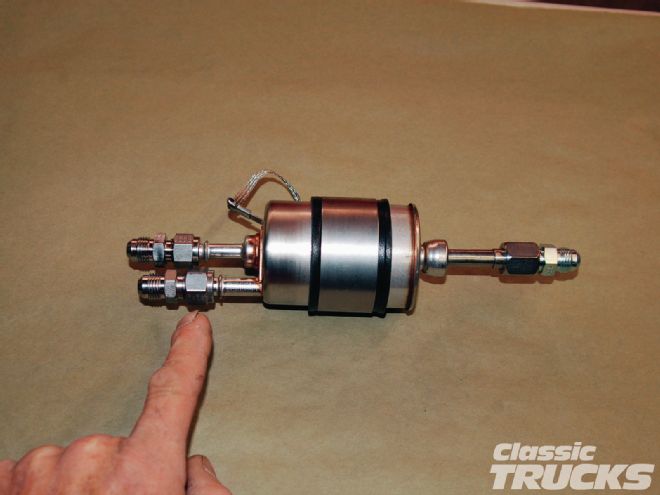
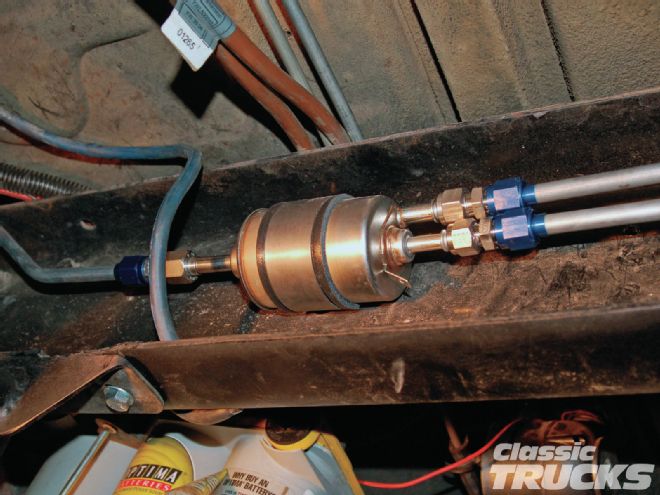
01. The fuel system is considered a returnless system. Basically that means there is not a return line running from the pressure regulator to the fuel tank. On a Corvette fuel system the fuel filter bleeds off the extra fuel. The bottom tube is the feed, the one above it is the return. The one on the right obviously goes to the engine.
02. The filter is mounted to the inside of the framerail on the passenger side up by the battery. I wanted it in an area that was easy to access so it was easy to replace when needed.
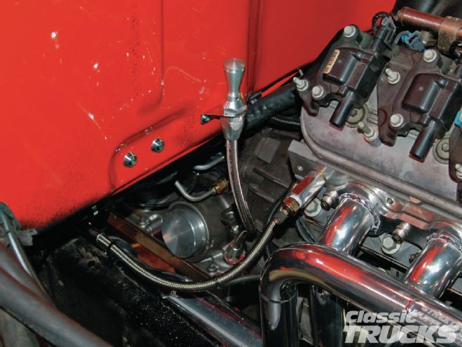
03. The stainless flex line connects the steel hardline on the frame to the injector rail. Again Street and Performance has this whole line setup. It's an optical illusion, the stainless flex fuel line is not sitting on the header like it appears in the picture.
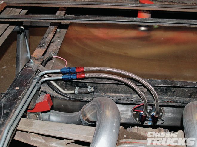
04. The aluminum tank has the fuel pump mounted in the tank. 3⁄8-inch pipe ports allow -6 fitting to be installed and the -6 stainless flex connected. Wiring is the hot from the computer/fuel pump relay and a ground.
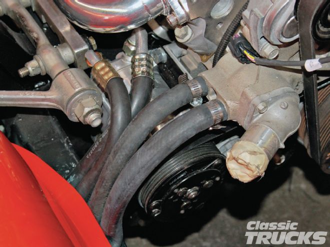
05. The heater hoses and A/C lines were no problem when hooking them up. The LS's have a 3⁄4-inch and 5⁄8-inch heater hose bibs. We have two 5⁄8-inch hoses from the previous hookup. A short piece of 3⁄4-inch heater hose and a 5⁄8 to 3⁄4-inch plastic reducer got the heater feed line connected and the return was simply trimmed to fit and connected.
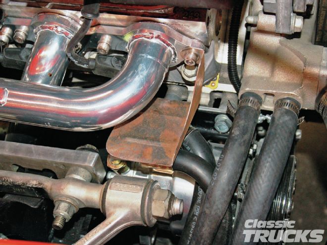
06. Since the A/C fittings are close to the header tube, I made a small shield to protect them from the heat.
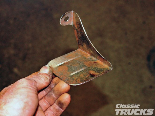
07. The shield just bolts to the header flange with one of the header bolts. We painted it black.
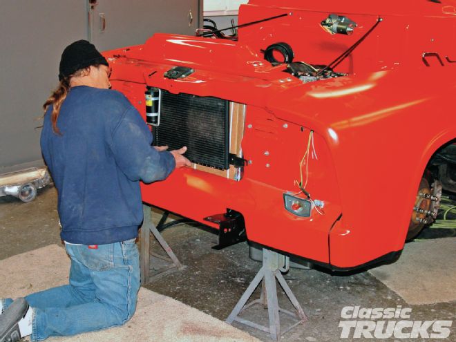
08. With the cold-air intake and different radiator, the A/C condenser needed to be remounted a little lower. Here, Bob is getting it into position so I could come up with some new mounts.
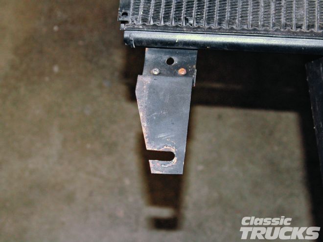
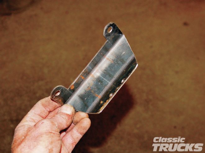
09. This is the one that came with the condenser. It bolts to the bottom bolt for the air dams on each side.
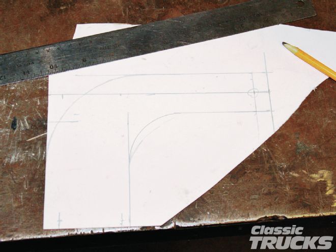
10. Some cardstock is used to lay out the shape and hole locations of the new brackets. When satisfied, I cut out the pattern and transferred it to some metal. Hole locations are also center punched from this template.
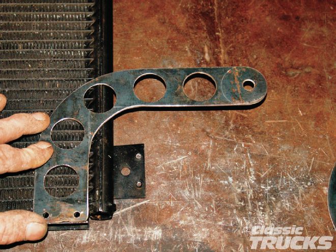
11. Here's a test fit of the new bracket I made. I will use 10⁄32 screws to mount the bracket to the condenser at the bottom.
12. The top of the condenser needed a bracket also. A piece of wire bent for the angles needed and a couple of measurements and this is what I got.
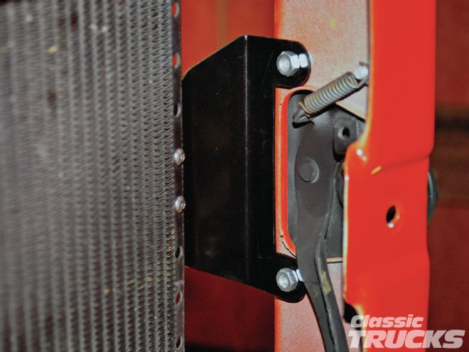
13. It attaches to two of the stock hood latch bolts and over to the condenser. The bolts were replaced with longer ones so Nylok nuts could be used when it was finally installed.
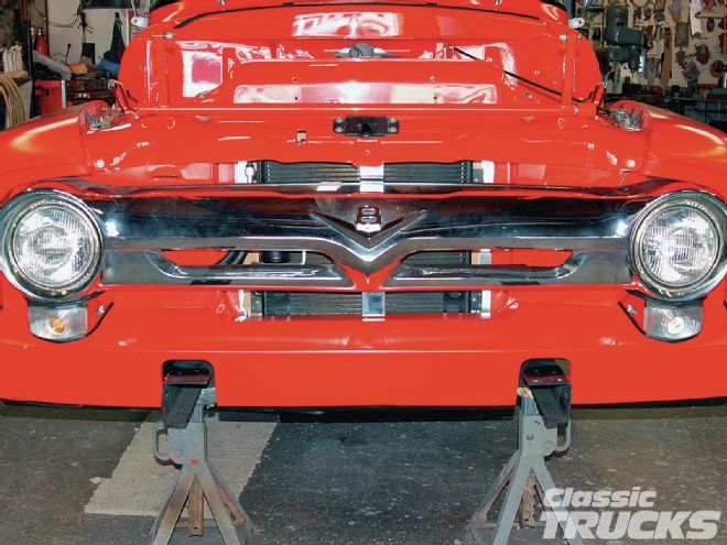
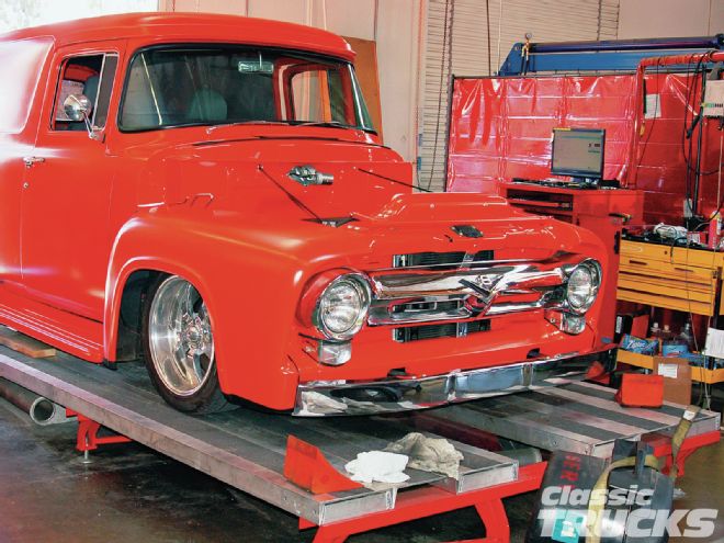
14. The grille was installed to check clearances around the remounted condenser.
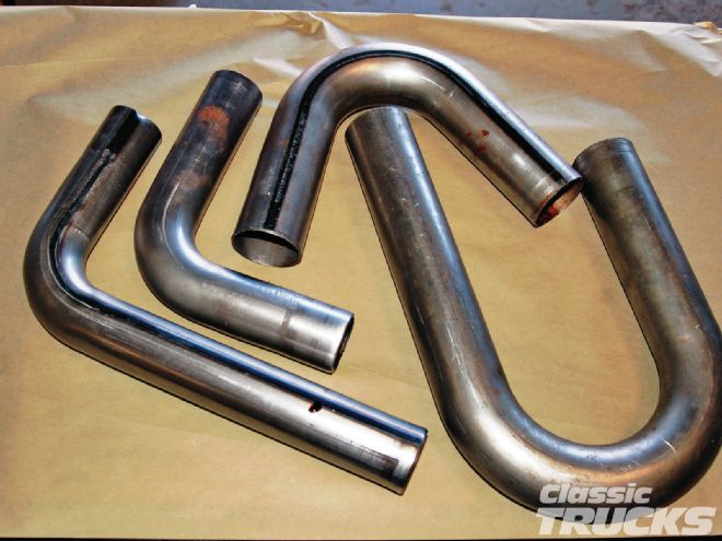
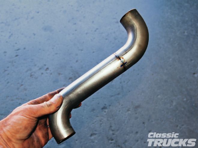
15. This is where the radiator hoses came from. I like getting the tightest radius bends I can in the tubes. This is .065-wall header tubing, 1 1⁄2-inch for the upper and 13⁄4-inch for the lower.
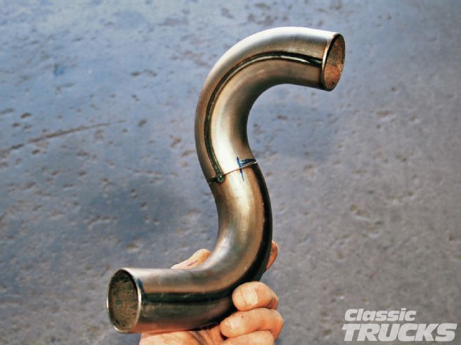
16. Sometimes you get lucky and the tubes just fall in place when you cut and fit them – one weld and the lower hose is done.
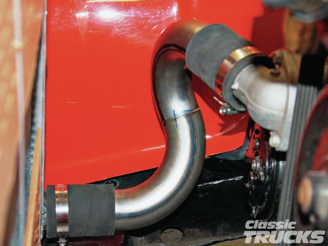
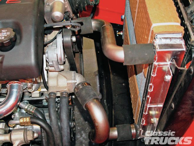
17. This is how it fits the engine and radiator.
18. The upper hose was done the same way and ended up with only one weld also.
19. Here's how the two hoses look when connected. These were just painted satin black, but they could have been chromed or powdercoated.
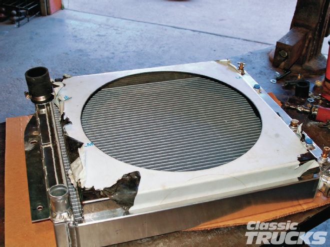
20. Since you have to run an electric fan, we needed a fan shroud. Bob happened to have a shroud we use on the stock Ford radiators. With a couple of cuts and welds it fit like a champ. Who would've thought?
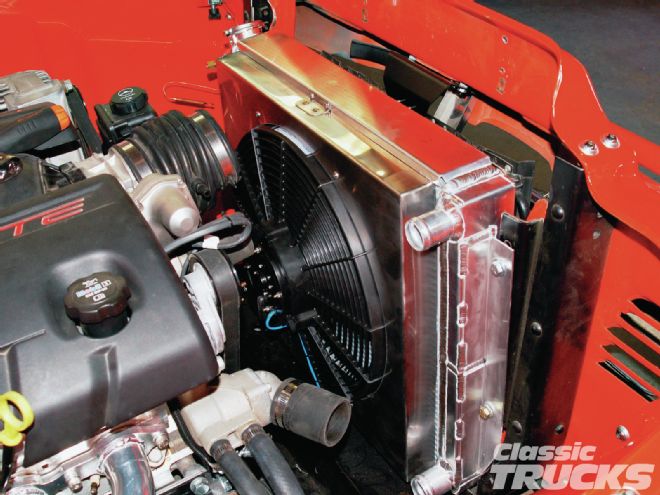
21. This is how the whole thing fit. The radiator, shroud, and fan. The upper shroud bracket is hidden by the cold-air intake plenum.
22. It's all done and purring like a kitten.
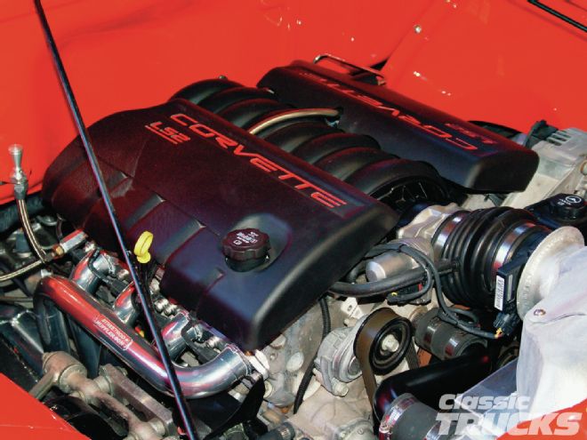
23. This is one clean installation. These motors are so compact and bitchin' looking. The cold-air intake is something a previous employee of Bob's came up with. This swap was the second in a row at the shop and when he made the one for the first truck, he made another for this one at the same time. There is a flat filter inside and it draws air from the bottom, in front of the radiator.
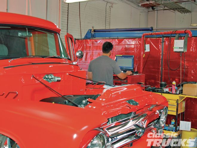
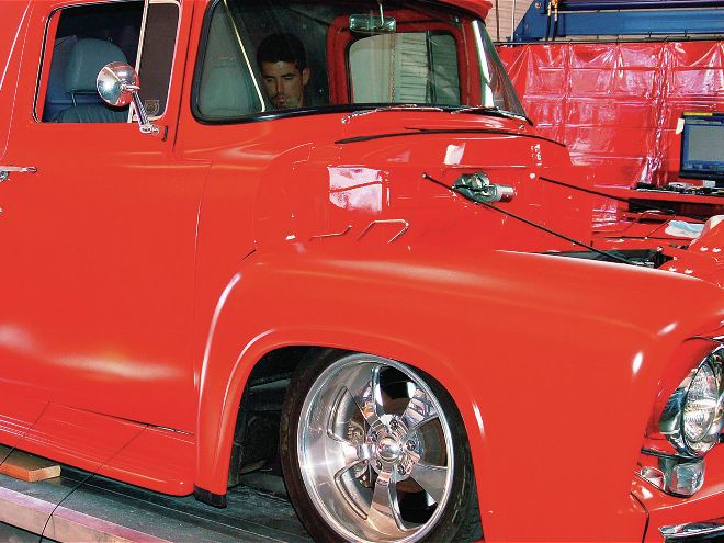
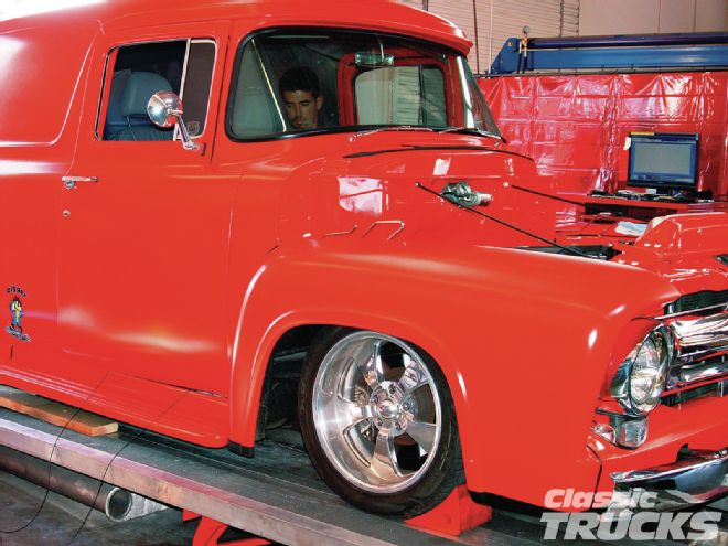
24. This is 21st century hot rodding. With the computer-controlled engine, the program can be modified to our liking. The dyno we're sitting on is going to tell us what we end up with in rear-wheel horsepower and torque.
25. While running on the dyno, Ryan can simulate highway speeds and adjust for the best performance.