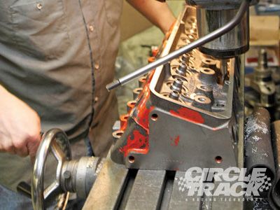
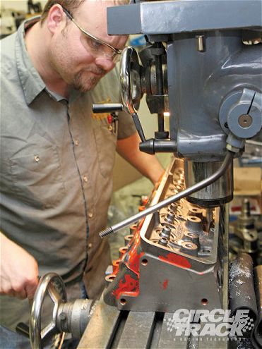
 Like the block, some prep on the cylinder heads will require machine-shop level expertise. Here, Kevin Troutman of KT Engine Development opens up the pushrod holes on the Dart Iron Eagle cylinder heads to gain clearance required by the larger lobes on our Comp Cams racing camshaft.
Part Three
In the first two installments of Circle Track's Limited Late Model engine build we prepared the foundation for a race engine that makes the most bang for the buck. In the previous two installments, we finished prepping the block and installed the crank, rods, and pistons. This time around, it's time to get busy with the cylinder heads and valvetrain. Although it has already been installed, the heart of the valvetrain for this project is a custom-ground cam from Comp Cams, designed specifically to make the most from this engine package.
Right about now you're probably saying to yourself something along the lines of, Custom cam! I thought this was supposed to be a real-world budget build. The beauty is anyone can get a custom cam for his engine since Comp does not charge extra for this service. You can get an off-the-shelf cam if that suits your needs, or you can choose from any of the hundreds of grinds available from Comp's catalog. Cam spec help is also free by calling Comp's tech line.
Finally, before we get started, there are a couple small points that probably should have been pointed out earlier. Good engine building practices require fastidiousness when it comes to cleanliness.
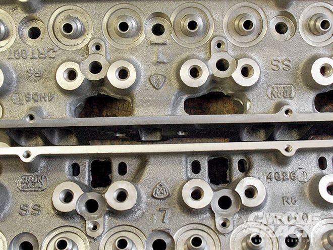 Here's a comparison of the work done to open up the pushrod holes. This was done on a milling machine, but you can do it by hand if you want. This not only creates room for larger pushrods, but it also cuts a little weight off the top of the engine. Just be careful not to break into the intake ports.
This means making sure your assembly area is clean and as free of dust and dirt as possible. Building your engine will also most likely take place over several days, or even weeks, so make sure to keep the engine covered between work sessions. Large garbage bags are cheap and work well for this. They will also catch oil that drips off the assembly and keep it off of your shop floor. Finally, every part that goes onto your engine should be cleaned before it's installed. This includes brand-new components that are straight out of the box.
We won't bore you with photographs of all the individual parts on this build being cleaned, but be assured that it's happening. A large parts washer is great for this, but make sure it's relatively clean. Lots of race teams have a parts washer they use for cleaning the gunk off of gears, hubs, or whatever else needs to be cleaned, and no one is really sure when anyone last changed the solvent. If this describes your parts washer, don't use it (at least until you flush and replace all the solvent). If you don't have a parts washer handy, you can get by with a gallon of lacquer thinner and plenty of shop rags. Let's get to it.
Even with new heads, you may need to have the valve seats cut. We are using larger 2.020 intake and 1.600 exhaust valves (the maximum allowed by most tracks), so new seats had to be cut to enlarge the Iron Eagle's 1.94/1.50 sizes. Also, if you're running stock heads, they usually come with only a one-angle valve job. Investing in a three-angle valve job (30/45/60) is usually money well spent because it will greatly improve airflow through the port.
Most rulebooks have a minimum cc rule for the combustion chambers-usually 62 cc's-so to maximize compression, you'll need to get your heads decked to bring the chamber to the minimum size. Here, Kevin Troutman measures the chambers before cutting.
The Spec Sheet
Want more details? No problem. Here are the specs for our mechanical flat tappet cam from Comp Cams. Our cam was installed at the suggested 104-degree intake centerline.
The springs we chose for this build are Comp's beehive design. They are smaller at the top which cuts weight by using a significantly smaller retainer. The beehive shape also helps cut harmonics. The result is better valve control with less spring pressures. Once installed, our springs spec'ed out at 140 pounds at a 1.740 installed height and 260 pounds over the nose (0.480 inch maximum valve lift).
We're running head studs from ARP instead of bolts because they produce more even clamping torque across the head. The only problem with studs is they can make the heads impossible to remove with the engine still in the car. Regardless of which you choose, make sure to use plenty of thread sealant because the bolt holes on Chevrolet small-blocks go right into the water jackets.
The Cometic head gaskets we're using are a multi-layer steel design (MLS) which not only seal better in high-compression applications than conventional head gaskets, but are also quite thin when compressed. The compressed thickness once the heads are bolted on will be approximately 0.040 inch, which will help keep compression up.
One trick to help eliminate oil leaks is to apply a thin film of silicone above and below the "ears" on each gasket.
Now the heads can be gently lowered into place. Make sure they fit over the dowel pins on the deck of the block.
ARP provides torque specs for its fasteners when using either oil or moly lube. But you'll get more consistent results with moly. Make sure to coat the threads and the mating face between the nuts and the washers. (Or the underside of the head of the bolt, if that's what you're using.) Don't be afraid to use this stuff liberally. Too little can mean an improperly torqued head bolt, but too much just means you've got a mess to clean up.
Torque the fasteners in three steps. Begin at 30 ft/lbs, and then move on to 55 and finally 80 ft/lbs. The final torque value for motor oil, by the way, is 85 ft/lbs.
The order in which you tighten the head bolts is also critical because a cast iron head can actually flex as you tighten it. Begin with the center stud just above the center exhaust ports. Then move down to the stud just below the exhaust port split on the left. Continue moving in an outward spiral until you've tightened them all.
The lifters, per most rules for this level of racing, are solid flat tappets.
The most dangerous time in a flat-tappet cam's life is the first few minutes when it's breaking in with the lifters. The high-spring pressures used in racing combined with the aggressive lobe grinds make "wiping" a lobe and ruining the cam a real possibility. To prevent this, you can take a few preventative measures. You should have already liberally coated the cam lobes in assembly lube. Now, after cleaning the lifters, spray the faces with a dry graphite lubricant.
After the graphite has dried, the next step is to apply a lubricant like the white lithium grease you see here or some other thick assembly paste that won't drip off.
Now, as you install the lifters, make sure to coat the lifter bores and the bodies of the lifters with assembly lube as well.
Here's an instance where you always have to be willing to adapt during a build. Even though we had enlarged the pushrod holes, we still had interference problems with the mockup pushrods and the side of the head once the pushrod guides were installed. We've used these Comp Cams guides in several other builds, and they are fine, but they just won't work in this application.
Instead, we had to switch to a set of adjustable guides from Isky. Compared to the Comp guides, the Isky pieces (bottom) are made in two interlocking pieces. They also have larger bolt holes which also provide some adjustability. They are more expensive than the standard plates, but in a situation like this they are a lifesaver.
Here, you can see the guide plates installed on the heads. If you need to move the slots closer together, you can grind the ends of the interlocking tabs. The screw-in rocker studs are from ARP. They should be torqued to 50 pounds with moly lube, unless any of the holes on your head extend into the water jacket, in that case use thread sealer.
Once you've found your correct pushrod length, you can continue to use your pushrod checker to degree in the cam while you wait for your new pushrods to come in. The first step is to find top dead center of the piston in the number-one cylinder (the first one on the right). You can do this with a piston stop screwed into the spark plug hole.
This is also a good time to determine your correct pushrod length. Using a checking pushrod, mark the top of the valve stem with machinist's dye or a Sharpie and install the pushrod and rocker arm. Cycle the engine over several times by hand until the rocker leaves a mark on the tip of the valve stem.
If the pushrod length is correct, the tip of the rocker arm will travel over the center of the tip. If the mark is too high (closer to the lifter valley), lengthen your pushrod checker and try again. If the mark is too low, try shortening the checker.
After verifying that our cam measured out with the same 104 degree intake centerline that the supplied cam card stated it should have, we moved on to the next step.
Before the build is complete, you should always degree in your camshaft. I own a camshaft degreeing kit that works with the heads on the block, so I'm finally ready for this step. If you can degree your cam without the heads in place you can do this after the timing set is installed. Regardless of when you do this, you will need to pull the stock springs for checking springs so that you can also check the piston-to-valve clearance. One of the easiest ways to do this is with an on-head spring removal tool like this one I got from CV Products. You can also use an air hose adaptor to pressurize the cylinder and help hold the valves shut while you're compressing the springs.
You'll also need a degree wheel and a pointer. These are part of a kit from Powerhouse Products. We don't have space here to go through the complete procedure for degreeing in a cam, but for more information go to www.circletrack.com and type "Camshaft 101" into the search box.
You need to have lightweight checking springs on both the intake and exhaust valves to check piston-to-valve clearance. Using your degree wheel, set the engine so that the number-one piston is at 10 degrees after TDC, compress the intake valve until it contacts the piston and measure the movement. Do the same thing with the exhaust valve at 10 degrees before TDC. With a solid flat tappet lifter, you should have at least 0.080 clearance on the intake valve and 0.120 on the exhaust or you risk banging valves into the piston tops at high rpm levels.
If everything checks out, you can lock in the timing set. Remove the three bolts holding the cam sprocket to the camshaft and slide a cam button into place. The distributor gear has a tendency to push the cam forward inside the block and a cam button will prevent that.
Next, apply red Loctite to the bolts and thread them back in.
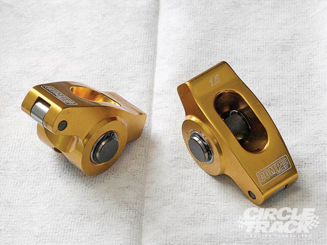
Diamonds may be a girl's best friend but for a gearhead these rockers sure look a lot like jewelry. These are Comp Cams' new Ultra Gold aluminum rockers, and they have just about everything you could want in a stud-mounted rocker. They are lightweight aluminum, fully rollered, polished to eliminate stress risers, and guaranteed for life by Comp. And even with all that, they usually sell for less than Comp's steel Pro Magnum rockers.
The cam sprocket bolts should be torqued to 20 ft/lbs, but with the cam button in place it can be difficult to get a socket on them. If you have this problem, try using a socket for a 1/4-inch drive wrench. It usually has a thinner wall.
Hopefully, by now your correct pushrods have come in. We're using 5/16-inch diameter pushrods in a 7.900 length (7.800 is stock). We would've preferred using 3/8 diameter pushrods to prevent any flex but the clearance issues prevented us. Before dropping the pushrods into place, squirt a few drops of assembly lube into the cups of each of your lifters.
Now, drive down one of the tabs on the cam button lock for each one of the bolts. It may seem like overkill to do this much to make sure these bolts stay in place, but if the timing set fails, it usually means catastrophic damage to the engine.
To protect the ends of the pushrods and the pushrod cups in the rockers, squirt a little high-pressure lube on the pushrods before installing the rockers. Also, a little lube on the threads of the rocker studs will help keep the rocker arm poly locks from galling to the studs.
With mechanical cams, your camshaft manufacturer will usually give you suggested lash settings on the cam card. We're going to start out with Comp's recommendations of 0.018 inch of lash for the intake and 0.020 for the exhaust but probably will do our own tests on the dyno later.
And once all the valves are lashed, we are done with the valvetrain component of the buildup. Next month, we'll set the intake on top and start buttoning things up with the accessories.