As we admitted at the onset of this project, we had set some pretty ambitious goals for our Mild-Mannered Mauler; in fact, we were looking to cut new ground. To recap, the engine is a basic .030-inch over 440, a balanced assembly with a factory forged crank, and a set of short dome SpeedPro pistons, massaged for a final net dome volume of 11 cc. The engine combination's main goal was to produce power like a race piece, at the 600hp level, and yet deliver road manners, idle quality, and an rpm range typical of a mild street mill. To put numbers on it, we were after 600 hp, 600 lb-ft, and an rpm range making peak at or just above 6,000 rpm. The idea was minimal bark, but a bloody bite in a normally aspirated package. This engine will eventually wind its way into a street 'Cuda convertible project, where it will be expected to idle with 13.5-14 inches of vacuum, and cruise the open road cleanly at low-to-moderate rpm with a deep overdrive ratio manual trans. It will need to sit in traffic in the heat of summer with the A/C on. Good fuel economy, quiet operation, and low maintenance would be nice too.
Taking an analytical look at those numbers, crossing the 600hp mark by itself isn't too tough with a good 440, but making it by 6,000 rpm is something that would take an outstanding execution of the combination. Remember, horsepower is derived from torque and rpm, so setting a relatively low cap on the rpm at which peak power will occur means it will take tremendous torque to get there. Making a peak torque number of 600 lb-ft from 446 cubes is really pushing the limits of what is obtainable. It can and has been done, but it's ground not often traveled. Add in the driveability and idle quality requirements, and it's going to be a development effort to get there.
The outline for meeting these requirements was pretty clear: high airflow, short duration/high lift cam/ high compression ratio and cylinder pressure. Airflow had to be exceptional for good cylinder filling, especially with the short camshaft duration required to meet the rpm and driveability objectives. A long duration cam would make more power from the combination, but would sacrifice idle quality. We needed relatively short duration, and would make up for the short overall timing with exceptionally fast valve opening rates and high lift. In theory, the super-aggressive Competition Cams XEHL hydraulic lobes would provide the fastest valve action, and as a hydraulic would meet the low-to-no maintenance and noise objectives. Working with custom 1.7:1 rocker arms, the combo we settled upon delivered .600-inch net lift, with a rated duration of only 275 degrees at .006-inch lift, or about the same overall duration as stock. A single pattern cam set on a 112-lobe separation angle, and installed at 106-degrees intake centerline would help achieve an idle not much off a near-stock 440 Magnum, despite the lift.
High compression would serve double duty, helping to achieve the torque and power numbers we targeted, while the reduced clearance volume also aids in cleaning up the idle. Modern OEM engines are pushing ever closer to the 11:1 mark, with Chevrolet's new LS7 Corvette plant actually at that level now. Initially, we were shooting for about 11.7:1 compression, and we had prepped a set of Mopar aluminum heads for the job with 88cc chambers. We were confident that compression ratio could be tolerated on pump gas with thermal barrier coatings, a tight .035-inch quench, and cold-air induction. Midstream, the highly modified Mopar head castings were set aside in favor of Indy's CNC-ported 295cc EZ heads, which featured better flow and a more workable architecture.
With the bottom end already built, the smaller 78cc chamber of the Indy head shot the compression ratio of our combo way up-to no less than a full 13:1. What to do? A change back to a flat-top piston would have brought the combo back to exactly the targeted ratio, but the super-high compression was intriguing. No, it wouldn't be expected to run on pump gas by itself, but it would very likely work with water or a water/alcohol injection. Newer high pressure/high atomization systems have become popular on highly boosted street turbo and mechanical supercharger applications, so we decided to keep the high ratio to experiment with such systems in a high-compression normally aspirated engine. The potential benefit-if it works-is more torque production, and better part-throttle efficiency and fuel economy. It's a pretty wild approach, so don't start building your own Mauler until the full series is completed, all the data is in, and all the cards are on the table.
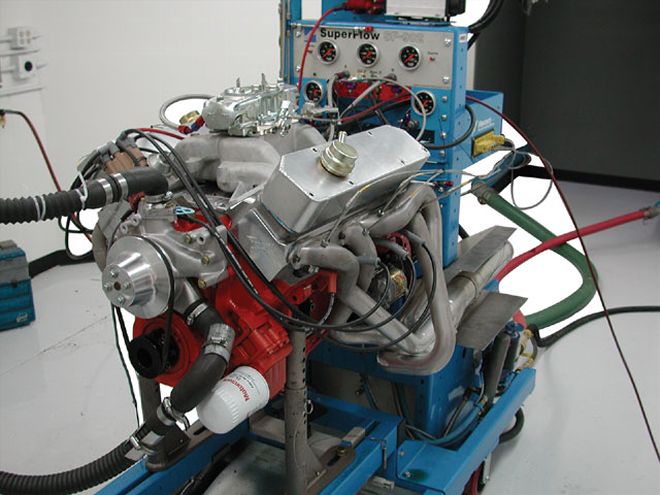
To The Dyno
That pretty much sums up the build and the theory behind it. The engine was taken to Westech Performance Group for preliminary testing to get an idea of how the theory works out in practice. This project is by no means the type of thing you build with full knowledge of what to expect, slam on the pump for a report card, then ship out the door. Our first testing was more of a progress report, a check to see how close it is to being on target for the objectives we set, and to determine what, if anything, will need closer examination or changes. The engine was equipped with the ported Indy dual-plane intake we featured in a previous story, topped with a Mighty Demon 850-cfm carb. With the radical flat-tappet cam, we were very careful in the cam break-in procedure. The cylinder heads were equipped with Comp's springs (PN 930), set up at an installed height of 1.900 inches, using Comp's titanium retainers (PN 721). The springs deliver 142 pounds of seat load and 353 pounds over the nose with our cam, which is pretty stout for a flat tappet. For break-in, the inner springs were removed, and the springs were installed on the heads with the outer springs and dampers only. This reduces the load considerably, until the cam and lifters establish a wear pattern.
For this testing, we used VP 114-octane race fuel. The distributor was dialed in for 34 degrees of total timing, and it fired instantly. The engine speed was brought to 2,200 rpm for a break-in cycle of 30 minutes. The break-in went perfectly. With the outer springs and dampers only, the springs were providing 103 pounds of seat load and 270 or so pounds at max lift. With the outer springs only, dyno operator Tom Habrzyk and I decided to do a couple of preliminary pulls to gauge the air/fuel ratio, and to see how the low spring load copes with the intense camshaft action. Our first pull was to 4,500 rpm, followed by another, raising the limit to 5,000. The engine did run up to 5,000 rpm before any audible valve float occurred; however, the data showed, as expected, compromised control with the very light spring loads. Power on this first-look pull reached 490 hp at 4,900 rpm, with torque coming in at 540 lb-ft at a low 3,700 rpm. The mixture was very rich, registering in the low-to-mid 10s over the course of the rpm range.
With preliminary numbers that looked encouraging, we allowed the engine to cool down and installed the inner spring to the valvespring assemblies. Our loads were now quite high for a flat-tappet application, just in the range of what would normally be used with a serious flat-tappet cam. The 930 is a conventional dual-spring with a 1.509-inch outside diameter, and has proven to offer good rpm potential with a typical high-performance flat-tappet camshaft. We also took this opportunity to make a jetting change, leaning the carb six jet sizes at the front and rear. The dyno was set to make a pull to 6,000 rpm. The results showed the jetting to have helped lift the power curve in the lower rpm ranges, and revealed some interesting insight on valvetrain control. The curves carried virtually parallel through 4,600 rpm, although the engine was making an average of 10 lb-ft more torque across the range with the more appropriate mixture. At 4,600 rpm, the single outer spring dropped off like a stone, while the dual spring with its increased loads carried on with the slope of the power curve as straight as a bullet. However, at 5,400 rpm, the gig was up, and the valvetrain became unstable with an immediate nosedive in power from there up. Peak numbers were now 551 lb-ft, at 3,500 rpm, and 560 hp at 5,500 rpm, right where the valvetrain went unstable. The low apparent peak torque is deceptive, since the engine's torque curve was extraordinarily flat. At 4,800 rpm, the engine was making 550 lb-ft, within one lb-ft of the torque reading at 3,500. In fact, looking at the average torque over the full test range from 3,100 to 5,500 rpm-the point at which valvetrain instability became apparent-the engine delivered an average of 544 lb-ft, which was very unusual.
We could see the engine in this configuration was going to come up short of our goal of 600 lb-ft of peak torque. However, the slope of the horsepower curve before the onset of instability showed the potential was there to meet the 600hp target, if only it would rev more cleanly upstairs. We had a set of Comp's high-tech Beehive springs (PN 26120), which have tested to provide unusually good valvetrain control in other applications. We made the spring change, installing the new Beehive spring at 1.880 inches, which provided spring loads of 155 pounds on the seat and 377 pounds over the nose. This is about as much spring as can be run with any reliability on a conventional flat tappet, and the Beehive winding significantly reduces inertia at the valve. We used a steel retainer (PN 964) and a modified lower locator to fit the Indy heads. Interestingly, the change to the Beehive spring did almost nothing to improve the rpm potential of the valvetrain. Peak torque improved slightly to 556 lb-ft at 3,500 rpm, with the same flat curve varying little and holding nearly constant to record 554 lb-ft at 5,100 rpm. Peak power nudged up to 559 hp at 5,400, at which point the valvetrain became unstable and power began to plummet.
It seemed as if there was little we could do to correct the valvetrain instability problem, but the lower part of the power curve at which the valvetrain was operating correctly seemed normal. We had run all of our tests to this point with the ported Indy 2D two-plane intake. We also had an Indy 440-2 single-plane intake and were curious about how it would compare. The 440-2 was port matched, but not otherwise modified. The single plane manifold added marginally to output above 4,500 rpm, recording a new high in peak power of 570 hp at 5,500 rpm, while peak torque moved to 561 at 5,100 rpm. The lower end of the torque curve dropped sharply for the 10hp gain at peak torque, dropping as much as 50 lb-ft off the bottom end. Outright top-end power, however, was clearly limited by the problems we were encountering at the higher rpm.
With the limitation on rpm, despite a wide range of different springs, it began to look as though the springs' ability to control the cam's action at the valves was not really the limiting factor here. The evidence began to point to the hydraulic lifter itself. To explore this possibility, we decided to run a diagnostic check, substituting a solid lifter for the hydraulic. Can a solid lifter run on a hydraulic stick? For testing such as this, the answer is yes. Hydraulic cams lack the clearance ramps required to ease a solid lifter from lashed clearance on the base circle to the flank where the lifter begins to really accelerate. The trick is to lash the solid at .003-.004-inch lash, hot, which will effectively allow it to follow the lobe similarly to a hydraulic. The difference is, it will not have the hydraulic mechanism we suspected to be the cause of instability in our setup. The lifters were swapped and lashed, and the results were telling. The engine pulled cleanly to the 6,000-rpm limit of our test and produced 607 hp at 6,000 rpm. Peak torque was now at 549 lb-ft at 5,200 rpm. The solid lifter allowed the cam to translate its design specifications to the valve more accurately, while it appears with the hydraulic, something was being lost in the translation.
While the engine handily met our 600hp by 6,000-rpm goal, the check with the solid lifter certainly isn't a long-term solution. Actually, it just pointed to the direction where we needed to do more work. The simple conclusion here is the combination of very intense valve action, high spring loads, and a relatively heavy valve and valvetrain is just too much for the hydraulic mechanism to cope with. At higher rpm, the lifter likely just collapses the internal plunger, losing lift and duration, making the power curve nosedive. The easy solution is to substitute a solid roller in place of the hydraulic flat tappet, since the roller will allow high spring loads, while the solid body will eliminate all question of hydraulic instability. These intensities are exactly what a solid roller is designed for. Our engine did meet the goals of mild manners at idle, running smoothly at 850 rpm without a big-cam lope, while generating over 14 inches of idle vacuum at 14 degrees of initial advance.
We are uncertain exactly where this project will lead until we get more testing done on the dyno. We'd like to see peak torque edge up to the stratospheric levels and improve the high-rpm dynamics without sacrificing the great idle we have now. It'll make for some interesting testing to come.
DYNO RESULTS SUPERFLOW 902 ENGINE DYNO TESTED AT WESTECH TORQUE RPM T1 T2 T3 T4 3,{{{100}}} 532 537 491 460 3,500 552 556 513 500 4,000 542 547 526 516 4,500 544 548 549 534 5,000 545 553 560 546 5,500 534 532 544 542 6,000 475 424 451 531 HORSEPOWER RPM T1 T2 T3 T4 3,{{{100}}} 314 317 288 271 3,500 368 371 342 333 4,000 413 417 401 393 4,500 466 469 471 458 5,000 519 527 533 520 5,500 560 558 570 567 6,000 543 484 535 607LegendT1: Indy 2D dual plane; Comp 930 springT2: Indy 2D dual plane; Comp 120 Beehive springT3: As T2, but swap to Indy 440-2 single planeT4: As T3, but swap to solid tappet lashed at .004 inch