
Part I in the October 2002 issue began to unravel the mystery of deciphering airflow numbers that are derived from flow bench testing. We addressed the question, "Why test for airflow?" and detailed the process of the flow test. Part II continues and will show that more flow is not always better.
Is flow bench data real?
This depends on how you define real. If executed properly the flow test results will be accurate, but they may not be indicative of the actual airflow in the engine.
Many factors come into play during the dynamics of engine operation that cannot be duplicated on the bench, but can be mathematically predicted. A common mistake that many operators make is not checking the intake port of the head with the intake manifold and companion components attached. Air does not like to make turns, and the longer the path it must take to the valve, the more frictional flow losses occur.
The proper method of testing is to quantify the intake port of the cylinder head with a radiused inlet as a baseline. Then test again at all lift points with the intake manifold and carburetor or throttle body installed. By quantifying the flow loss with the intake manifold you can better plan your port modifications. A good rule is not to accept more than a 20 percent loss through the intake components. Ideally you would want no loss, or actually have the intake design complement the port by adding airflow.
 A rigid valve opening fixture with an accurate dial indicator is essential for an accurate flow test. Deflection of the valve opening fixture will result in false readings. Bad flow data is worse than no data at all.
As an example, if the cylinder head flows 275 cfm @ 28 inches of water, and with the intake manifold and carburetor it only flows 206 cfm, a 25 percent flow loss is present. In this case the intake manifold would need to be changed or modified to reduce its impact on maximum flow. If you are forced to use this manifold for class racing, then it would not behoove you to spend time trying to get the head to flow to 300 cfm since the intake will choke it down to 206 cfm. It's important to recognize low lift flow numbers and to evaluate the impact that your modifications have throughout the flow range. Herein lies the importance of software and computer-aided flow bench data acquisition. Even though flow graphs can be established manually, human nature being what it is, one usually avoids this tedious task. When looking at a graph of a port's characteristics at different lift points, the area under the flow curve can be easily defined by triangulation. A port that has a larger area under the curve will generate more power than one that has higher peak flow, but less area.
Beyond frictional flow losses, other factors affect airflow in an engine and cannot be duplicated by flow bench testing. These are air density, thermal transfer to the incoming charge from the engine, the mass of the fuel, piston crown configuration, rod/stroke ratio, piston velocity, engine rpm and intake manifold tuning characteristics, to name a few. This does not discount the validity of flow testing and with some simple mathematical equations, an accurate prediction of engine performance can be derived .
Understanding the data
With the basic guidelines and procedures for flow testing established, the age-old question of interruption of the data comes up. To fully use flow bench readings, an understanding of the internal workings of an engine is required. Ultimately, piston velocity determines the amount of flow through a cylinder head along with the size and shape of the port and the valve. Once the bore is filled, the combustion event will determine how effectively it uses the charge to generate an expanding flame front and push the piston down.
Factors related to cylinder head design go beyond flow capability and include burn rates and spark plug location. The location of the initiation of the ionization process has a major impact on the cylinder pressure rise in relation to the crankshaft's arc of rotation past TDC. The ideal position is the center of the bore with a hemispherical combustion chamber for the best surface-to-volume ratio. If packaging concerns do not allow this placement, the closer the electrode of the plug is to the bore center with a bias to the exhaust valve, the more beneficial it will be. None of this can be established on a flow bench and will be responsible for different power levels produced with the same airflow numbers. Cylinder head intake runner volume has an impact on velocity, and in turn VE. Customarily measured in cubic centimeters this value can give an indication of the area of the port but it's deceiving. Liquid volume measurements alone do not calculate area, and two different port shapes could pour out to the same cc measurement.
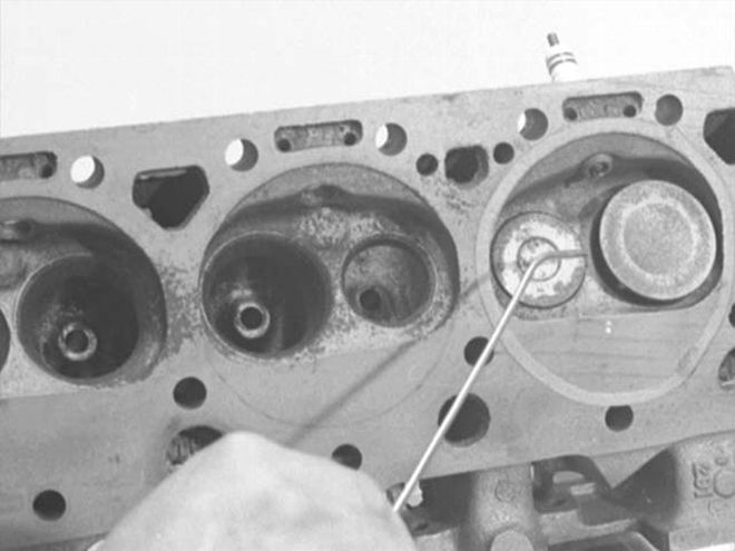 Most flow bench operators don't use their equipment to its full potential. Here, a third-generation Firebird cylinder head is being checked for velocity and uniform flow around the intake valve with the intake port attached to the fixture.
A port with a larger bowl area and smaller cross section can consume the same liquid volume as one with a large cross section and smaller bowl. Port area derived from a coordinate measuring machine (CMM) is how OEs define volume. Since this is impractical on the enthusiast level, it's common to take a cold pour rubber mold of the port and calculate the area by means of vernier caliper readings.
A concern for velocity is also represented by integral design protocols such as port taper and entry angle along with the valve angles in reference to the bore centerline. Velocity of the charge, as the pumping effect of the piston creates a low pressure region in the bore, will affect VE. The larger the port area, the slower the velocity and the higher the rpm the engine will require in order to use this port effectively.
Larger cubic-inch engines require increased port volumes to promote good cylinder fill rates. The ideal scenario would be an intake port that has sufficient area to support a column of air that is voluminous enough to satisfy the displacement needs of the engine, but small enough to keep the velocity high. Exhaust port concerns are centered on the ability to evacuate the cylinder and are a function of thermodynamics and the supersonic speeds usually seen during blow down. The exhaust process should begin 40*-60* before bottom dead center (BBDC). Until BDC is reached, the burned gases are discharged due to the pressure differential between the cylinder and the header or exhaust manifold. After BDC the pumping loop is responsible for the evacuation of the residual gases along with the overlap of the cam.
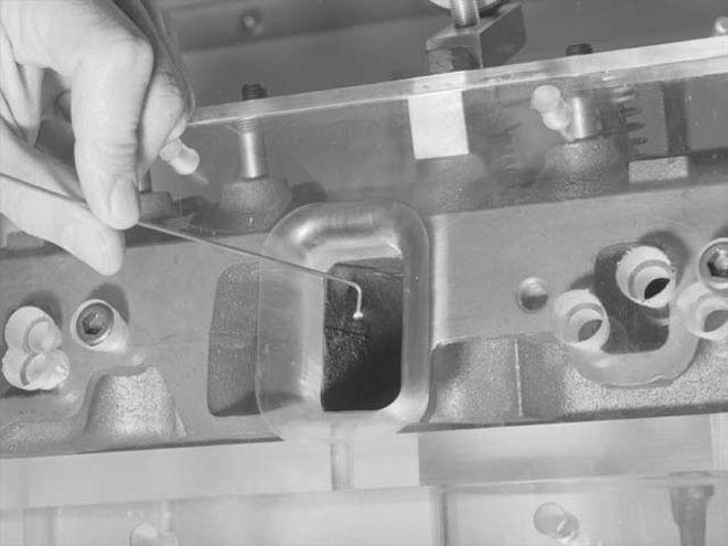
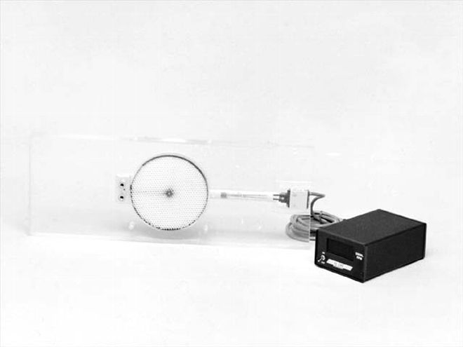
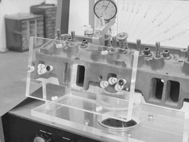 For accurate flow results, a radiused inlet needs to be mounted to the intake port to eliminate shearing of the air. The photo shows a plexi-glass inlet fixture, but one made from modeler's clay or wood would work.
The period of time just after the opening of the exhaust valve, where cylinder pressure is higher than the exhaust pressure, is identified as blow down. Blow down should occur while the piston is still dwelling at BDC. During this process, the exhaust gas expands isentropically (without thermal change). Exhaust port designs can either aid or hinder this. The theory of obtaining area under the curve along with low lift flow numbers will support blow down, relying less on the pumping loop. Because of this, it's common to calculate the intake to exhaust ratio. Current trends desire an exhaust port that has 80 to 85 percent of the intake flow. Some tests on some engines have concluded that a ratio of as low as 60 percent produced no power losses with certain combustion chamber designs.
Valve seat angles can make or break flow numbers and are critical throughout the lift range but pay the largest dividend at low lift when both the intake and exhaust valves are shrouded. Flow bench testing of different ground-in seat angles is a factor that many overlook.Understanding and using flow bench data accurately is a key element in increasing the specific output of a Pontiac engine. It is especially critical for enthusiasts who build traditional Pontiac mills since there are not many good flowing high- efficiency aftermarket cylinder head castings available. Whenever dealing with airflow take a systems approach. It usually is the most productive route. A good rule is--if in doubt, go small. Smaller port area, intake manifold cross-section and exhaust primary tube sizes will reward more often than too large a component.
School Days
Successful cylinder head modifications require both an empirical and theoretical foundation. Trying to understand the controlled chaos that is airflow in an engine calls for expertise in varied disciplines. The first is the theory of airflow and combustion, and the second, the actual porting process.
In the past, one was left to develop these skills on his own. Mired in a sea of unknowns with no mentor and, at best, the aid of a small number of how-to books, many hours were spent actually killing airflow in a cylinder head. Thankfully that has all been changed by the Mondello Technical School.Located in Paso Robles, California, Joe Mondello runs a week-long hands-on cylinder head porting program. Appealing equally to experienced head porters or an individual who never held a die grinder, Mr. Mondello's more than forty years of cylinder head experience is bestowed upon the students. The class is kept small, 4-6 students per session, to allow intense instruction. Also available is a second week-long program, engine blueprinting. The fee for each class, when taken separately, is $2,500 per person and includes hotel accommodations, lunch and two snacks a day. Upon successful completion, the graduates are taken to dinner by Mr. Mondello.--R.B.
Home based flow bench
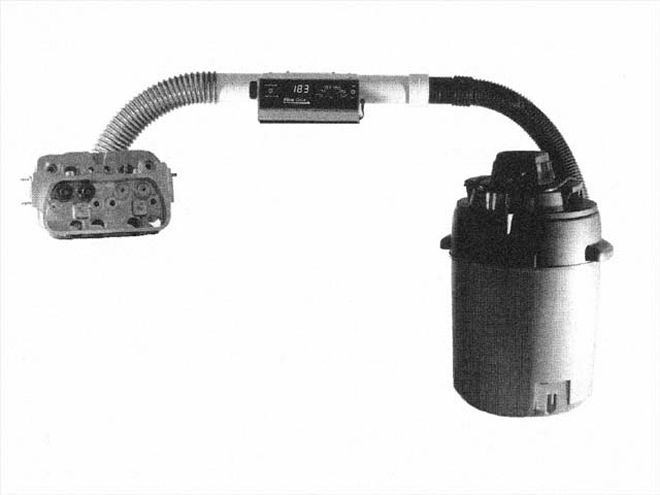
Understanding flow bench testing is great but without owning a flow bench, there's little you can do with your knowledge. With professional benches costing anywhere from $6,000 and up, that investment is very hard to justify for a racer or even a small shop in which the main focus is not cylinder head rework. But fast, affordable flow bench testing is now available to everyone from Audie Technology. Responding to the need to offer low cost but accurate flow testing, the Flow Quik was developed. This ingenious system uses a shop vacuum as the airflow source. Unlike a traditional flow bench, it does not control the amount of depression (vacuum). Instead it measures the depression and flow and displays the flow at a standard depression. You select the test standard with a range knob and Flow Quik does the rest, relying on the principals of fluid dynamics. It's as accurate as a professional bench. Flow Quik users who have experience on traditional flow benches report that testing using this method is actually up to ten times faster than the old ways. With the base Flow Quik kit starting at only $579, your own flow testing program can be easily established.--R.B.
How Much Power?
Through the use of mathematics, flow bench data can be used to predict many engine scenarios. Inertial supercharging, estimated VE, engine speed for peak power, maximum safe engine rpm, among others. But the resounding question in this hobby is how much airflow do I need to support a certain power level, and if I have airflow numbers, what power can I predict? The chart we included in Part I references airflow at 25 inches of water to power per cylinder.
A very rudimentary but simple equation is: Airflow at 28 inches water x .257 X the number of cylinders = horsepower potential from airflow.
To demonstrate let's plug in some numbers: 275 cfm x .257 x 8 = 565.4 horsepower.
If you want to go from horsepower to needed airflow: hp/.257/8 = required airflow (565 hp/.257/8= 274.80 cfm). This equation takes little into consideration but works well to get you into the ball park until you're brave enough to predict more accurate results with higher level math. If you want to do more, consider purchasing the SuperFlow manual for a complete listing of flow bench math. --R.B.
Swirl And Tumble
Extending the envelope of airflow testing the next logical step is to recognize the presence of externally induced mixture motion. The pattern that the charge takes as it exits the valve and combustion chamber area and enters the bore is identified as mixture motion. Swirl is identified as the rotational motion of the incoming air charge about the cylinders' axis as it enters the bore. An example of this would be water going down the drain of the sink. Swirl follows the perimeter of the bore. A description of tumble is that the rotational motion of the incoming mixture is in a plane approximately perpendicular to the axis of the crankshaft as it enters the bore, coming down one side of the cylinder and rolling back up the other. A good example of this would be pouring wine into a goblet and having it run up the opposing side. Many factors control whether a port has swirl or tumble, with the dominant one being valve placement in relation to the bore centerline.
Hemispherical combustion chambers along with OHC designs that place the valves at the perimeter of the bore will induce tumble. Inline valves that are the hallmark of Pontiac engines will induce swirl, if mixture motion is present. Since these are induced prior to the bore, they're all identified as external charge motion.
Another phenomenon is internal charge acceleration. This is a relocation of the charge nearer the spark plug and the acceleration of the mixture as the piston reaches TDC and the charge is forced from the squish regions. Internal charge acceleration is created by increasing the squish/bore area relationship. It has a positive effect on burn time.
Both swirl and tumble are used to improve octane tolerance by creating a quicker burn, increasing combustion stability, and improving EGR tolerance. The negative of motion is the energy consumed to rotate or tumble the charge, which leaves less energy to move air.
Any internal or external charge motion will also have a positive impact on the amount of spark lead the engine needs. Cylinder heads with more motion require less spark lead, which adds to their octane tolerance. Within the industry, a debate has been raging on mixture motion with some looking to increase it, while others want to eliminate it. It is the author's opinion, along with that of Pete Incaudo of CNC Cylinder Heads who has studied mixture motion for years, that the end use of the engine needs to be defined before you can call this motion friend or foe.--R.B.
On a street engine below 12.5:1 compression, the resounding consensus is that motion will pay dividends in octane tolerance, which would allow for a higher compression ratio on pump gas, along with better throttle response and driveability. On race engines that operate in a limited rpm range and have a compression ratio of over 12.5:1, the concern for octane tolerance and efficiency are moot and the energy that's used to swirl the mixture would be best used to increase the airflow capacity.
Swirl meters are available using paddle rpm or paddle wheel torque. With either design the higher the reading the more prevalent the swirl. Swirl direction also becomes an issue and is identified as positive or negative motion. If the cylinder head posses no swirl then the mixture takes the appearance of a waterfall, discharging the perimeter of the intake valve at low lifts. On these heads at higher lifts the charge creates a flow window that's similar to a jet stream. Mixture motion is nothing new, engineering books from the 1930s speak of it, but not until recently has it been quantified and intentionally induced by cylinder head designs.
We hope this two-part article has helped in the understanding of flow bench testing and that the resources named herein will be useful, should you decide to test for airflow in your Pontiac.--R.B.