There are only two ways to increase an engine's displacement: You can bore it (engine boring increases the cylinder diameters) or you can stroke it (engine stroking increases the crankshaft stroke).
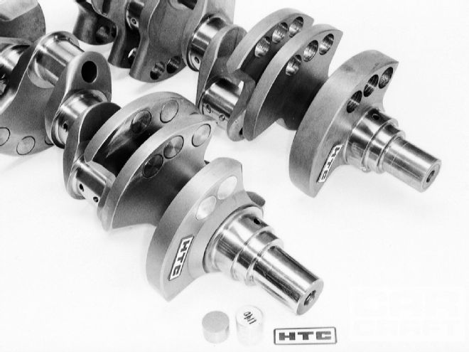
Engine Stroking offers the potential for significantly larger displacement increases than those obtained from typical engine boring, but it also requires greater sophistication when selecting and integrating components. Like you, we want to find out how to get a good stroke (as opposed to getting stroked), so we consulted three of the most experienced crankmen in the country-the legendary Hank "The Crank" Bechtloff, his son Scott, and his brother Allan. While Hank and Scott are still active trick crank grinders at HTC Products, today Allan specs Winston Cup cam applications for Crane.
The info in this story can be applied to get more cubic inches from any brand of engine.
Engine Stroking & Engine Boring: What Do You Gain?
Just how much is a good stroke worth? Using the standard displacement formula...
Displacement = bore2 x 0.7854 x stroke x (No. of cyls.)
...we see that on a Chevy 454 V-8 (4.25-inch bore x 4.0-inch stroke), a 0.060-in overbore (4.31-inch final bore size) yields a 466.9ci engine, but keeping the stock 4.25-inch bore size and increasing the stroke by 1/4 inch to 4.25 inches results in 482.3 ci. (If the engine was both bored 0.060 and stroked by 1/4 inch you'd get 496 ci).
Engine Stroking & Engine Boring: Component Stack-Up
Rod length or piston compression height (piston-pin location) do not affect the bore size or stroke length, and hence do not alter displacement. However, rod length and/or piston-pin location changes may be required after a change in stroke to properly locate the piston top in the block for a desired deck height clearance at Top Dead Center (TDC).
To determine the total height (H) of a given reciprocating assembly:
H = Piston compression height (pinhole centerline to deck) + Piston deck height (deck to top of block) + connecting rod center-to-center length + 1/2 Stroke
You only use half the stroke because the crank spins in an arc, and half of the increase in total piston travel occurs at the bottom of the cylinder. The required change in the combined connecting rod center-to-center length, piston compression height, and piston deck height is inversely proportional to one-half of any change in stroke. You can make up the difference by changing any combination of the three variables (rod length, piston compression height, or deck height) the required amount to maintain dimension "H"-whichever is cheapest or easiest for the application.
For a practical example of factors that must be juggled when stroking an engine, suppose a Ford engine builder installs a 3-inch-stroke 302 crank in place of his stock 289 engine's 2.87-inch stroke crank. He wants to maintain the same 8.206-inch overall assembly height, 0.016-inch deck height, and 1.60-inch piston compression height, changing only the rod length (R). What length rods are needed?
8.206 = 1.60 + 0.016 + R + (1/2 x 3)
8.206 = 3.116 + R
8.206 - 3.116 = (3.116 - 3.116) + R
5.09=R
It so happens this is exactly what Ford does on standard (non-Boss) 302 engines-use shorter 5.09 rods in place of the normal 289's 5.155-inch rods.
Even though the same piston and deck height is retained, the overall static compression ratio goes up due to the increase in swept volume that is compressed to the same preexisting clearance volume at TDC. That's also why even though a short-rod (5.565-inch center-to-center length) Chevy 383 small-block can use 350 pistons, the compression ratio ends up higher compared to the ratio obtained with the same piston and 5.7-inch rod in a standard 350.
Offset Grinding
Our hypothetical Ford engine builder installed a longer-stroke crank and shorter rods from the same engine family. But the big displacement increases that stroking makes possible are more often accomplished using modified and/or nonproduction parts. There are several ways to change the stroke of an existing crank. Tradi-tionally, the simplest and easiest method is a process known as "offset grinding." Normally, when a rod journal is reground to compensate for wear, the machinist reduces its diameter to the next standard available undersize bearing while maintaining the journal's existing centerline location. But when a crankshaft is offset ground, the rod journal centerlines are moved farther away from the main-bearing-journal centerlines.
 This crank journal has been built up using a new-tech Gleason powdered-metal welding procedure. The continuous weld leaves no pitting. After welding, the crank is stress-relieved for four hours at 875 degrees F.
Rather than minimally offset grinding the journal down to the next standard bearing undersize (which yields only a small stroke change), performance offset grinding typically reduces the final journal diameter to a smaller size used by a different (but still commonly available) connecting rod. For example, when a 2.10-inch large-rod-journal small-block Chevy rod journal is offset-ground, the journal is commonly reduced to 2.00 inches, the size of a '55-'67 small-block Chevy rod journal. In theory, going from a 2.10 to a 2.0 journal should allow a 0.100-inch stroke increase if the throw is reground with the maximum possible offset (relocating its centerline by 0.050-inch). However, in the real world this much of an increase isn't practical: p (Pi, the math operator used to define the boundaries of a circle) is an infinite figure, so trying to exactly intersect the tangent point of two different diameter circles is impractical; there is tool-chatter to overcome; and usually you're starting with a used crank that requires normal undergrinding to make up for wear. For these reasons, crank grinders typically allow a 0.020-inch "safety factor"-so the real obtainable stroke increase from a 0.100-inch change in journal diameter is about 0.080-inch.
The small-block Chevy guys are fortunate that their favorite engine design has two different rod journal sizes available. That's not the case for many other engines. In fact, the vast majority of engines built with offset stroker cranks use rods from a different model engine or aftermarket specialty rods. This may require the use of pistons with a different than stock (for the original engine) pin diameter.
Welding
Engines with large rod journals (such as Buicks, Oldsmobiles, and Ford 351 Windsors) can achieve fairly decent stroke increases via offset grinding and nonstock rods. But in most cases, really radical stroke increases require other solutions. Welding is a traditional procedure for obtaining big stroke increases. This process involves adding material to the top side of the rod journal, then regrinding to the original rod journal size but with the journal centerline moved outward in relation to the main-bearing centerline, thereby increasing the stroke. Forged cranks are more suitable welding candidates than cast cranks, but in any case, traditional welding induces tremendous heat which adversely affects the crank's metallurgical strength. In recent years sophisticated submerged arc-welding and reheat-treating processes have been developed that address these issues, but the cost of a welded stroker has correspondingly increased to the point that for popular engines like the small-block Chevy, a custom-ground stroker crank made from a universal raw forging is actually cheaper in many cases. Still, welding remains a viable alternative on those off-brand engines for which universal raw forgings aren't available.
 Modern aftermarket universal crank forgings and castings are typically made with an elliptical rod journal so almost any stroke can be ground.
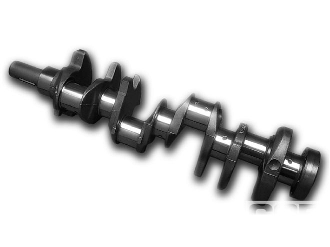
Custom Cranks
Once reserved for professional racers, custom forged or billet stroker cranks are now increasingly common in higher-end street/strip cars. Universal "econo" raw forgings are available for the more popular engine families. Their quality and metallurgy are acceptable for most uses. Typically, a universal raw forging is made with an elliptical rod journal so almost any stroke can be ground into it. The drawback is that grinding an elliptical journal into a finished round journal interrupts the continuity of the forging's grain structure, effectively negating its supposed advantage over a billet crank. Assuming you can afford it, you big-arm boys may as well buy a custom billet crank.
 The counterweights on HTC's "Ultrabalance" high-end billet crank (right) are shifted in the direction of engine rotation. This makes the crank easier to balance, which is always a difficult chore on a big stroker. So far, the relocated counterweights aren't offered on forged cranks.
Limiting Factors
So many possibilities, so little room. With all the stroker options these days, you'd think the sky's the limit when it comes to building giant engines. But real-world stroke increases are limited by the physical constraints of the cylinder block. We've already discussed the problems with reciprocating assembly stack-up, but there are also other clearance issues: Big stroker cranks may hit the oil pan rails, and the rails can sometimes be trimmed, but there's danger of breaking into an oil passage or water jacket. Clearance problems with the bottom of the cylinder bores or with the camshaft are also common.
 Expensive Mallory heavy metal is used to balance big strokers. These HTC cranks have Mallory in counterweights 2, 3, 4, and 5. The end counterweights are lightened with through-holes to reduce crank flex. Aluminum plugs fill the holes, reducing oil windage losses.
There's also the problem of the overlap between the main and rod journals. To find overlap (O):
As stroke increases, the overlap in the areas of circles defined by the main and rod journal diameters decreases. Less overlap reduces crank strength and rigidity. The amount of acceptable overlap is determined by the strength of the crank material, the engine's power output, and its intended use.
When regrinding a finished crank into a stroker, care must be taken not to run into the internal oil passages. Attempts at welding the original passage shut and drilling a new passage usually prove unsuccessful; eventually the crank cracks in the fillet area.
Piston Problems
As we've seen, increasing the stroke and making no other changes usually causes the piston to stick out the top of the block. Shorter connecting rods are usually not the best solution; rather, pistons with raised pin heights help move the top of the piston back down below the deck. The pistons can be made shorter but only to a point-there must be room for the ring package above the piston pin. Even using thin rings (1/16 -1/16 -1/8 inch or metric equivalents), figure on a minimum total piston deck-to-pinhole top dimension of about 0.750-inch (more if a valve relief extends below the piston deck, as is the case on big-block Chevys). Various devices allow running the oil ring through the pinhole area, and there are even two-ring pistons; while acceptable for regularly torn-down race engines, these solutions aren't recommended for long-term street use. You could also go to a smaller diameter pin and bush the rod-but "a smaller stick breaks easier."
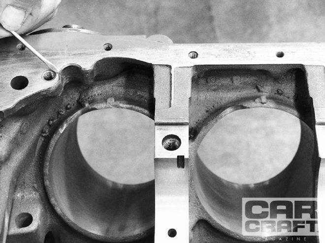
Installing a 4 1/8-inch stroker crank in a Ford 351W block required notching the lower oil pan rail (left) to clear the crank's counterweights. Notching the bottom of the cylinder bores (right) was needed to clear the rods.
Also, the bottom of the piston must clear the crank throw at BDC. Counterweight height (C) is determined primarily by the rod length for a given amount of stroke:
C = Rod center to center length
-Piston thickness below the wrist pin hole -Clearance value (usually 0.100)
Rod journal dia. + Main jouirnal dia. - Crank stroke 2 Stroke + Main journal dia. + Wrist pin dia. 2If a clearance problem exists, either the crank counterweight or the piston can be remachined. Do not remachine the counterweight in a circular arc or there will be insufficient weight left for balancing purposes. Instead, the counterweight must be cam-ground for clearance by an experienced custom crank shop.
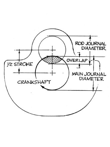 The overlap between the rod and main journals is a critical factor for maintaining crank strength and rigidity. As the stroke increases, the amount of overlap decreases, weakening the crank.
Con Rod Conundrums
Engines that operate over a broad rpm band (like acceleration engines or street engines) perform best with rod/stroke ratios in the 1.7:1 range. Engines that operate within a narrow rpm band (such as superspeedway, oval-track, or offshore racing-boat engines) like even higher rod/stroke ratios. As the stroke increases, the rod needs to get correspondingly longer to maintain the optimum rod ratio-but the longer the stroke, the less room there is to fit a longer rod. Too-short rods increase cylinder wall thrust-loading and restrict maximum rpm potential. Bottom line: On a big stroker, use as long a rod as you can get away with, based on the smallest practical piston.
Because of these complexities, leading aftermarket suppliers have developed integrated stroker kits. They have the experience to know what is or is not practical. Unless you're experienced in this area, it pays to consult a recognized expert like "Hank the Crank" (HTC). Yet, the payoff in added performance is worth the hassle-you can make the engine look stock on the outside, but pack it discreetly with additional displacement on the inside...and no one's the wiser until you blow their doors off.
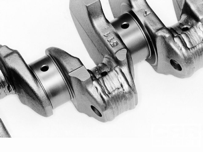
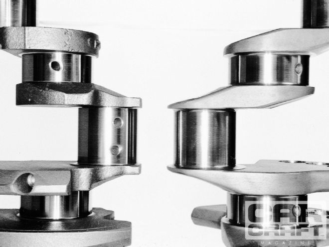 Note the decrease in overlap between the main and rod journals when going from a Chevy 350 3.48-inch-stroke crank (left) to a 4 1/8-inch stroker (right)-this despite the fact that the stroker uses larger 400 Chevy 2.65-inch main journals (compared to the 350's 2.45-inch mains).