Over the years we’ve found that some of the best opportunities come out of chance conversations. Take the time our esteemed editor, Brian “Private Eye” Brennan, heard about a good-running Flathead Ford engine that could be had for free, if we could figure out how to get it off the roof of what was once a hospital.
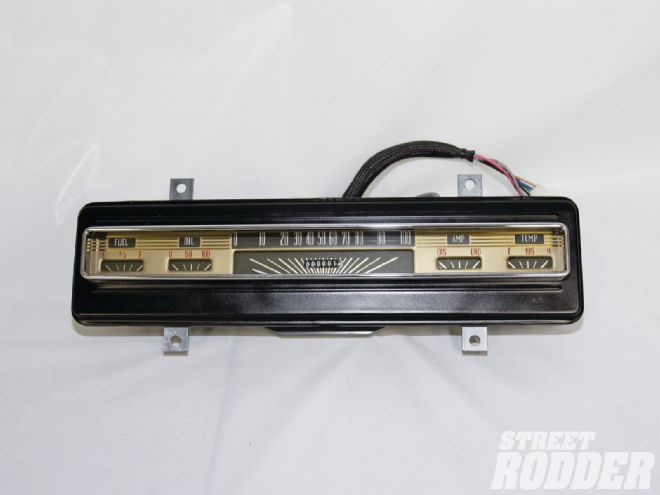
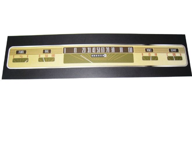
 Classic Instruments refurbished this ’41 Ford instrument panel. The new gauges, including the speedometer, are now electric.
With the capable assistance of former staff member turned freelancer Chris Shelton, Brennan, and yours truly, the engine that was once used to power a backup generator was dragged out of its enclosure by the three of us, and man-handled down a flight of stairs. Then, thanks to a crane operator willing to set the Flattie in the back of our pickup for a case of his favorite beverage, it was ours.
While the V-8 was a great find, along with it came an industrial instrument panel fitted with vintage gauges, which eventually found their way into our Model A pickup. Unfortunately it didn’t take long for the cool-looking mechanical temperature gauge to quit working. It was sent out for repair not once, twice, but three times. However, the results were always the same, the cab would smell like ether (that is what’s in the tube and internals of the mechanical-type gauge), the dial would drop down against the pin, and we had a cool looking but useless gauge.
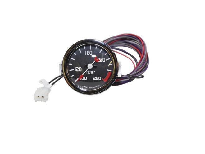 Thanks to Classic Instruments this vintage mechanical temperature gauge now has modern electronic internals to make it reliable and accurate.
About the time we gave up on fixing our vintage gauge and were resigned to a newer substitution that would result in a mismatched but useful instrument panel, another problem cropped up with a different project. We were in the process of installing a transmission in a ’41 Ford that was equipped with a sender for an electronic speedometer rather than a mechanical. While we could have changed the transmission’s electronic sender to a cable drive, the fact is the electric speedometers are so much easier to calibrate. We just needed a way to convert our stocker from a cable to wires. A chance meeting with John McLeod, of Classic Instruments, would lead to the solution of both our problems.
Founded in 1977 by the late-Frank Hettick, Classic Instruments’ business philosophy was that the latest in technology could make electric gauges every bit as good, if not better, than the mechanical variety. At that time the big argument for mechanical gauges was they were commonly used in race cars, but of course one reason for that was many race cars lacked an electrical system. Another more compelling argument for mechanical gauges was that they generally had a wider needle sweep and a broader scale, making them easier to read and seemingly more accurate. However, thanks to new, sophisticated movements and circuitry, electric gauges could have up to 300 degrees of pointer movement with unparalled accuracy; Hettick was onto something.
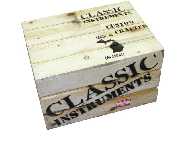 A class act, even the box Classic ships instruments in is cool.
In 2001 Hettick decided to retire and pursue other interests (he was a master of “space art”) and new owners assumed operation of Classic Instruments. Under the leadership of John McLeod the company’s product line has grown substantially and now includes a variety of bold instrument designs by such people as Tom Gale, former chief designer of the Daimler Chrysler Corporation. In addition they’ve developed a line of instrument panels for everything from early Fords to Camaros, they’ve produced custom gauges for some of the most prominent builders in the country, and, what’s near and dear to our heart, developed a custom department that retrofits original instruments to modern electronic movements. As they describe it “The retrofitting process is not a restoration of instrumentation. It is a customization to fit gauges in stock locations using the original housing. You can keep the look of your gauges nearly original in appearance or customize them to fit your project.
 The gauges were removed from the panel, it was then bead blasted and the inside surfaces were painted white, adding reflectivity for improved nighttime lighting.
Before we get into the Classic Instruments’ process for modernizing gauges, lets take a look at how our old gauges worked.
Mechanical Temperature Gauge
Our mechanical temperature gauge used what’s called a Bourdon movement, which consists of a C-shaped, flattened brass tube connected to an indicator needle on one end and a length of tubing with a bulb that fits into the cooling system of the engine on the other. Inside the bulb and tubing is a liquid that expands—as it gets warm that expansion causes the tube to move (like one of those curled-up party favors you blow on New Year’s Eve, only not to that extreme), as the tube moves a link transfers that motion to the pointer indicating the engine’s temperature.
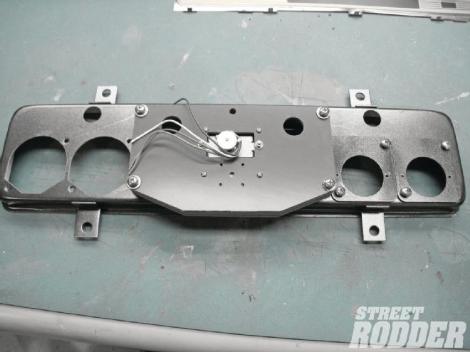 Seen here from the back, the stock instrument cluster housing has been fitted in the middle with an adapter plate for the speedometer. The holes on the right have adapters for the new fuel and oil pressure gauges, by comparison those on the left are for the original gauges.
1941 Ford Instrument Panel
All electric instruments work on a similar principal—voltage is applied to the movement of the gauge, from there the electricity flows to a what’s usually called a sender that varies the current flow through the gauge depending on the engine’s temperature, oil pressure, the level in the gas tank or whatever else is being measured. The increase or decrease in current flow causes the needle on the gauge to move.
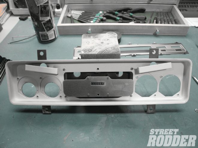 Seen from the front the new speedo wears an adapter plate to mount the gauge face. The size and shape of the plate varies with the shape of the housing that it’s being installed in.
There are several types of electrical instruments; those in the Ford’s panel were the thermostatic design, a simple, inexpensive style used in OEM gauges even today. Electricity flows through a special wire wrapped around a bi-metal strip in the gauge to a sender of some sort. As the bi-metal strip heats up and cools down based on the resistance in the sender, the bi-metal strip deflects, moving the needle on the gauge accordingly. Cheap to manufacture, accuracy is not great, one of the reasons we elected to install modern movements rather than simply convert the original gauges to 12V operation.
Another type of electric gauge is the balancing coil type. These use a pair of electro magnetic coils on either side of what’s called an armature that the indicator needle attaches to. Again, the current flow through the coils is determined by the sender. That in turn changes the strength of the electro magnets and their ability to make the armature rotate, which controls how far the needle moves. While these gauges are accurate, their shortcoming is their limited range of movement.
 New instrument faces were laser cut and printed to duplicate the originals.
A huge improvement in electric gauges was the development of the air core movement. As John McLeod explains, these gauges use a magnet on the rotor assembly that turns in a chamber filled with silicone fluid. The silicone functions as a shock absorber for the rotor assembly. The air core coils are wound at right angles to each other around the rotor assembly whose magnet is free to rotate under the influence of the fields developed by the coils. The variable resistance generated by sending units (a volt gauge uses varying voltages in the charging system), alters the current from the battery that flows through the coils, which in turn affects the magnetic field, generated by the coils. By varying the current going to each coil, the magnetic fields change and cause the pointer attached to the rotor assembly to move. Using an air core driver circuit, these magnetic fields can also be reversed, which makes it possible to obtain more than a 90-degree deflection of the pointer.
Retrofitting
 A new face for the cluster was created, the oil pressure gauge now has a max of 100 psi rather than the original 50; note this version has a voltmeter and the finished product has what looks to be an ammeter.
Updating early instrument clusters or an individual gauge is much more complicated than stuffing a new movement into an old housing. Just fitting of the new movements can be a challenge. In the case of our instrument cluster adapter plates were necessary to position the new gauges properly and the temperature gauge required a spacer to provide the room necessary.
New gauge faces are often produced; they may be printed by various procedures or laser etched on the lenses, but the big difficulty is often reusing the pointer. In some cases new hubs that fit the shafts of the new movements are put into the original. If necessary new brass pointers that duplicate the old are carved out with a water jet or laser cutter. In any case, the balance of the new pointers is critical.
In most cases when updating an older instrument panel the range of the oil pressure and temperature gauges will be increased and a voltmeter will be substituted for an ammeter. In our case the original amp gauge on the ’41 simply read “Dis” for discharge on one side and “Chg” for charge on the other. To maintain the original appearance our new voltmeter uses the same markings—the middle of the 13-gauge now represents 14 V.
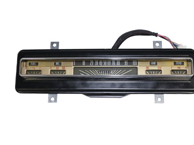
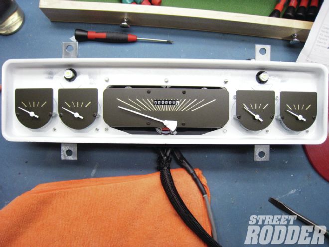
 Looking better than new, the refurbished instrument panel has up-to-date gauges and an easily programmable electronic speedometer.
We couldn’t be happier with our updated gauges. Ironically, in both cases the end results look so right that the improvements go unnoticed, but they’re certainly not unappreciated.
Gauge Basics
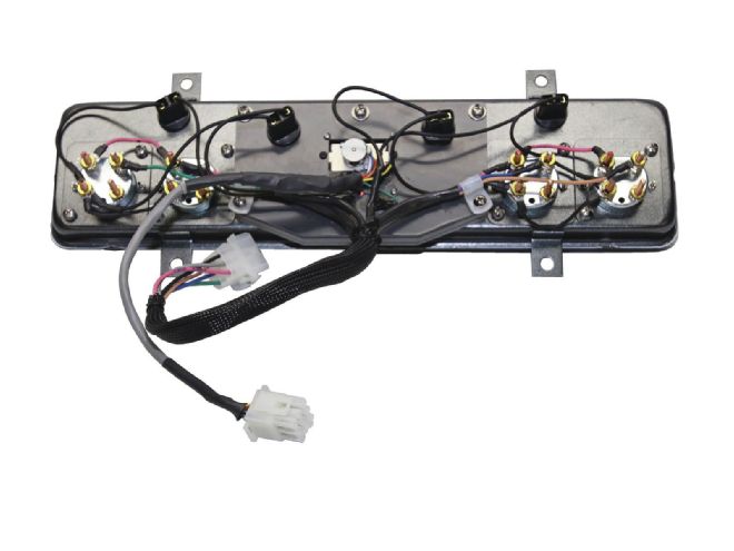 Classic’s new wiring makes this a plug-and-play operation. The plug at the bottom goes to the speedometer’s “brain”, the upper to the instrument senders and dash light feeds.
Here’s some general information on gauges from Classic Instruments:
Fuel Gauge
The most common fuel level sender that Classic Instruments supplies operates in a resistance range of 240 ohms empty and 33 ohms on full. Other senders available operate in resistance ranges of:
~0 to ~30 ohms (typically used with original GM fuel gauges before 1964)
~0 to ~90 ohms (typically used with original GM fuel gauges after 1966)
~78 to ~10 ohms (typically used with original Ford fuel gauges before 1986)
Classic Instruments carries fuel gauges that work with multiple types of fuel level senders
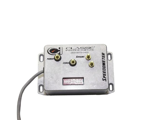 In some cases, like ours, there isn’t room for the speedometer’s control unit to fit inside the instrument cluster so a separate “brain in a box” is used. It plugs into the wiring panel’s wiring harness.
240-33, 33-240, 0-30, 0-90, 78-10, and 16-158 ohm range gauges available in 2-1/8 inches
240-33, 0-30, 0-90, and 78-10 ohm range gauges available in 3-3/8-inch quad
240-33, 0-30, and 0-90 ohm range gauges available in 4-5/8-inch quad
It is very important to run a dedicated ground wire to the fuel level sender to ensure it has a good ground. Don’t rely on the tank to provide the ground, since a lot of tanks are isolated from the ground by things such as rubber grommets. Without a proper ground on the fuel sender, the gauge circuit is not complete and the gauge will not work. The gauge will register infinite resistance for the sender and this will cause 240-33 and 75-10 gauges to peg below empty while 0-30, 0-90, and 16-158 fuel gauges will peg above full.
Oil Pressure Gauge
 This is the speedometer interface. It converts the pulses from the speed sensor on the transmission to a signal the speedometer can use.
Classic Instruments’ 100-psi oil pressure gauges register 0 psi at 240 ohms resistance, 50 psi at 105 ohms resistance, and 100 psi at ~33 ohms resistance (the lower the resistance, the higher the psi reading).
Classic Instruments’ SN52 (100 psi) oil pressure sender works in a resistance range of 240 ohms at 0 psi to 33 ohms at 100 psi.
SN54 (80 psi) oil pressure sender works in a resistance range of 240 ohms at 0 psi to ~33 ohms at 80 psi.
The Classic Instruments’ oil pressure sender gets a ground connection through the mounting threads. Without a proper ground to the sender, the gauges will read low or peg below 0 psi. Pipe sealer should be used sparingly on the threads of the sender and Teflon tape should not be used.
Temperature Gauge
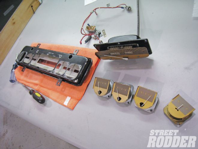
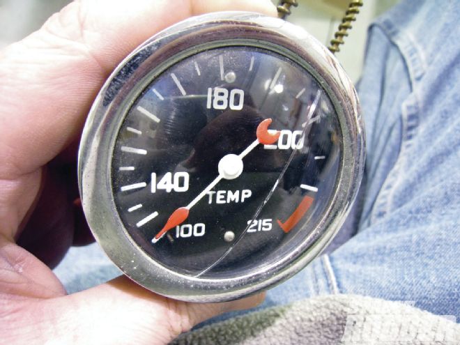 Our vintage temperature gauge stopped working. Then, to add insult to injury, the glass was broken.
Temperature senders should be mounted in the intake manifold of an engine when possible. Installing the sender in the head or in close proximity to other heat sources (i.e. exhaust headers) will cause the temperature gauge to read high. This is because the sender is being affected by the significantly higher temperature of its surroundings.
Bushings should not be used to make a temperature sender fit. Bushings could cause the sender probe to not be fully submerged in the coolant inside the engine (this could cause the sender to measure coolant vapor temperature, which is usually higher than the actual coolant temperature).
Classic Instruments carries five sizes of temperature senders that are all electrically identical (they operate in the same resistance range).
The sizes are:
SN12MM (12mm thread for LS engines)
SN22 (1/8-inch NPT, typically fits Chrysler engines)
SN23 (1/4-inch NPT)
SN24 (3/8-inch NPT, fits most Ford engines and newer GM engines)
SN25 (1/2-inch NPT, fits older GM engines)
The temperature sender is grounded through the threads that contact the engine. A good sender ground is necessary for proper gauge operation. Therefore, Teflon tape should NOT be used on the threads of the temperature sender. Liquid sealant can be used sparingly if necessary. (The SN12mm temperature sender DOES REQUIRE sealant or Teflon tape to be used on the threads. A copper crush washer is included with this sender to provide a ground connection between the sender and the engine.)
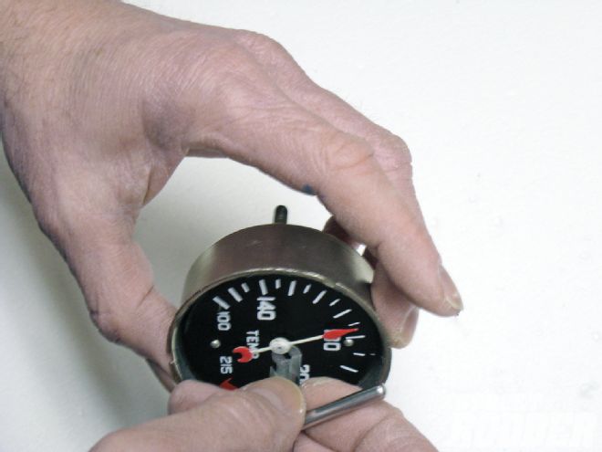
 Disassembly of the temp gauge began by carefully removing the rim from the housing.
Engine “core” temperature is typically 15-30 degrees F higher than the surface of the intake manifold where the sender is installed. It is normal (and expected) to get higher readings on the temperature gauge than readings obtained using an infrared temperature “gun”.
Volt Gauge
 This can be challenging, reusing the original pointer. Often they have to be “re-hubbed” to fit the shaft of a new instrument.
The volt gauge does not require a signal like the temperature, oil pressure, and fuel level gauges do. The volt gauge should be connected to a good ground and switched battery power. No connection is necessary to the alternator as with amp gauges.
Speedometer
Electronic speedometers operate on an electrical signal rather than a cable like the mechanical type. Classic Instruments’ 3-3/8- and 4-5/8-inch speedometers can operate on signals between 11,000 and 110,000 pulses per mile that have amplitude of at least 8 V.
The required signal can be produced a number of ways:
SN16 pulse signal generator: This is used on GM or Chrysler transmissions that have a mechanical speedometer cable drive. The pulse signal generator replaces the speedometer cable. It converts the mechanical movement of the cable to an electric pulse. The pulse is a “square wave” that alternates between 0 and plus 12 V. The SN16 is a powered signal generator. It requires plus 12 V to operate, unlike some two-wire pulse signal generators that create their own voltage.
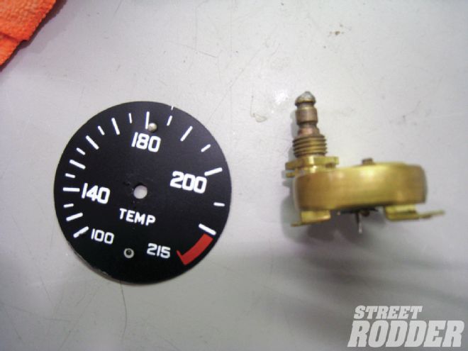 The original Bourdon tube internals and gauge face were removed; only the housing assembly will be reused.
SN17 Ford pulse signal generator adapter: This is used to convert the connection from Ford and similar transmissions that have a mechanical speedometer drive cable to work with the SN16. A speedometer cable driven gear needs to be installed on the SN17 adapter and is not provided from Classic Instruments.
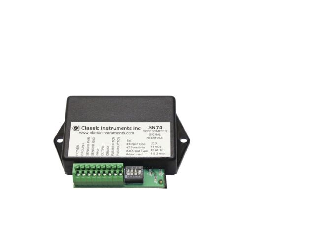
SN74 speedometer signal interface: This is usually used to convert speed signals from electronic transmissions or vehicle computers to one that is compatible with the Classic Instruments speedometer. Benefits of the SN74 are: push-button speed calibration and supplemental speedometer signal output (for cruise controls, lockups, etc.). The SN74 will convert any signal between 3,000 and 200,000 pulses per mile to either 8,000 or 16,000 pulses per mile. Classic Instruments speedometers can be configured to work on one of these signal frequencies. Some Classic Instruments speedometers have the SN74 functionality built into them with no signal interface needed.
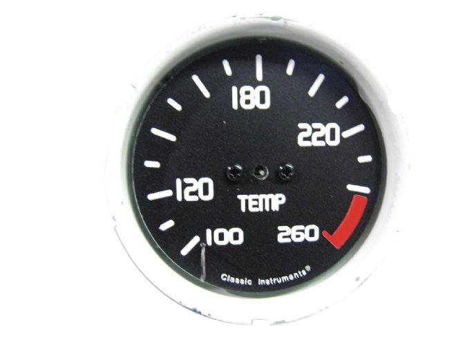 Prior to reassembly the inside of the housing was painted white to brighten the normally poor night lighting of early instruments. Other than the increased range, the new gauge face is identical to the original.
SN81 GPS speedometer signal: This can be used to provide a signal for any speedometer (not just Classic Instruments). Calibrating the SN81 can be done in the comfort of your garage. It is not necessary to drive the vehicle to get a proper calibration. The SN81 is especially useful for vehicles that lack a standard speed signal. Some common applications that would use an SN81: boat, ATV, golf cart, etc.
SN78SM magnetic proximity speed sensor: This sensor has a magnetic head, which senses ferrous targets. Targets can be bolts on a driveshaft or holes in a brake rotor. The SN78SM will provide a plus 12V pulse upon detection of each target. The number of pulses per mile should be calculated and should be at least 3,000 for good speedometer operation. The SN78SM sometimes requires a SN74 signal interface to convert a slower frequency signal to a signal compatible with the speedometer.
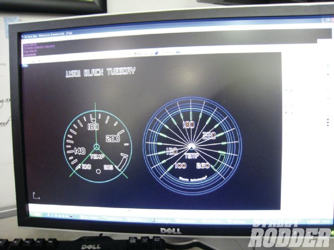 The trick to installing a new movement in an old gauge is to match the sweep of the needle to the original. Originally the temp gauge read 100 to 215 degrees, with the same sweep it will now read 100 to 260 degrees.
Tachometer
The tachometer can get a signal from a computer, ignition module, or coil. Some signals require an adapter to work correctly.
Classic Instruments’ 3-3/8- and 4-5/8-inch tachometers require a signal that has amplitude of at least 8 V. Some computer signals are 0-5V square waves (and need to be amplified. This can sometimes be done with a 1,000-ohm resistor installed between plus 12 V and the signal post of the tachometer.
The SN76 tachometer signal adapter will amplify a weak tachometer signal and double the frequency. This is useful for converting four-cylinder computer tachometer signals (computer signals tend to be four-cylinder, even if the engine is an eight-cylinder) to work with eight-cylinder tachometers.
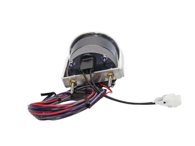 Viewed from the back the vintage housing has the new meter is in place with wiring for the sender and internal lighting.
Classic Instruments’ 3-3/8-inch tachometers work with four-, six-, or eight-cylinder signals and some 12-pole alternator signals; 4-5/8-inch tachometers work with four-, six-, or eight-cylinder signals and some 10-, 12-, and 20-pole alternator signals.
Classic Instruments tachometer combo gauges with push-button calibration function are compatible with signals of 1 to 14 cylinders and are also compatible with weaker 5V computer tachometer signals.