A friend once asked about the block of relays pinned to a board behind my car's dash. To him relays were the mysterious little boxes that some cars inexplicably required to operate a horn. More than one was plain ludicrous in his eyes. After all, how many horns could a car have?
The relay's primary appeal is its ability to do a lesser-switch's bidding but it's capable of so much more. Relays can be wired together to create very useful, simple, and utterly reliable networks. What follows are three of those configurations.
One transforms dual-filament taillights into tail/brake/turn signals. Another configuration duplicates the OEM circuit that preserves accessory power until a door opens. The third isn't so much universal but it's so useful that it would be foolish to not include it. It acts as a dimmer that toggles between low and high beams with the flick of a momentary switch. But first, a little bit of theory.
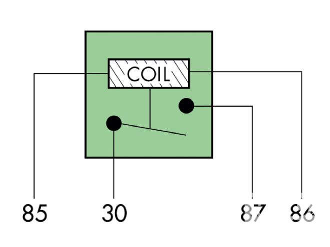 Here's how an SPST relay looks at rest from the inside. Terminals 30 and 87 represent the contact points, or the switch. Energy cannot flow between them when the relay is at rest.
Relay Basics
A relay is at its core a heavy-duty switch without a lever or knob. Power applied to an electromagnetic coil forces a pole to advance. A yoke mounted to that pole moves a lever that's called an armature, which either makes or breaks connections among contacts within the relay.
We refer to switches and relays as having poles and throws. Pole in this case refers to the number of electrically independent armatures, or switches, inside a relay. Throw refers to the number of stationary contacts that the armature (switch) can touch.
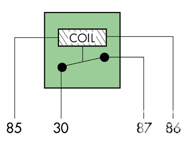 Power applied to terminal 86 and ground to terminal 85 energizes the coil, which advances the yoke and swings the armature. Once the armature advances, energy can flow between terminals 30 and 87. Easy, huh?
Most universal automotive relays have one armature, or switch, that corresponds with terminal 30. We refer to them as having a Single Pole (SP). The very simplest automotive relays have only one contact point at the end of that switch. When energized, that contact meets a fixed contact inside the relay body labeled terminal 87. We refer to that as a Single Throw (ST). These Single Pole Single Throw (SPST) relays behave like a simple light switch: off (at rest) or on (activated).
Some SPST relays can handle upwards of 70 amps, making them perfect for high-current applications, like oversized cooling fans. But they aren't without limitations. For one, they operate one way: on or off.
 An SPDT relay has another contact represented by 87a. When the relay is at rest power can flow between 30 and 87a. Energizing the coil causes the relay's arm to break that contact and reestablish it between terminals 30 and 87.
The Single Pole Double Throw (SPDT) relay is the same as the SPST relay but has a fifth terminal. Labeled 87a, it conducts electricity with terminal 30 when the relay is at rest. Energizing the electromagnet breaks that connection and reestablishes another between 30 and 87. In that way it operates like a three-way hallway switch.
SPDT relays can be configured to work in at least five ways. To replicate an SPST switch, simply connect the input power to 30 and the device to 87 but leave 87a bare. That's the backbone of a simple horn relay: the device will operate (blow the horn) only when the relay is activated (usually by a switch in the steering column that completes the ground circuit for terminal 85). An SPDT's action can be reversed by swapping the device to 87a and leaving 87 bare.
An SPDT relay can act like a railroad switch in the sense that it can send power in one of two ways. What's more, nothing dictates what direction the power can flow through the contacts. For example, connect the device to terminal 30 and you can feed it from one of two power sources. In fact, that's the basis for the first example.
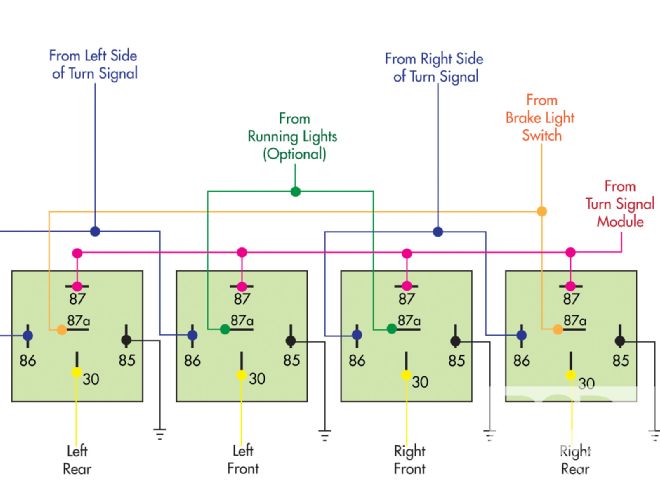
Rather than tell we'd prefer to show how to configure this simple turn signal relay bank. The optional running-light wiring transforms single-filament front turn signal bulbs into combination running lights and turn signals.
Turn Signals
Four relays can turn a toggle switch into a turn signal system. Painless Performance sells a compact version (PN 30120) that includes micro relays, brackets, a flasher module, and enough really high-quality cross-link jacket wire. We'll show how it works but I recommend buying it rather than trying to build it. I can build it but I'd rather buy it (in fact I've bought kits for two cars).
The basic turn signal-only version requires four SPDT relays, a two-wire flasher (if your fuse panel doesn't have an integrated flasher), and one latching SPDT on/off/on switch. A toggle or rocker will work; however, this setup is a great way to resurrect half-working turn signal switches. As long as at least one contact on both sides is good they'll work perfectly with these relays.
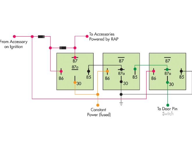 It looks intimidating but this schematic reveals the secrets of retained accessory power. Copy it to a tee (especially the diodes' direction) and it will work. It can be used to power the whole accessory circuit but I advise limiting it to as few devices as necessary.
Naturally, you'll want to fuse all inputs. It bears mentioning that the relays will drive the brighter filaments (brake filaments) in dual-filament lamps.
If your fuse panel has a hazard output, feed it to terminal 87 on all four relays. If not, feed constant power to a flasher's input and connect its output to terminal 87 on all four flashers. Likewise, feed switched power (ignition) to the common (center) pole of the toggle or turn signal switch. One output leg of that switch feeds one pair of relays; the other leg feeds the other pair.
A very slight modification will make that turn signal system operate as a four-way flasher. Simply feed constant power to a Double Pole Single Throw (DPST) latching switch and connect each of its output legs to an output terminal on the turn signal switch. The two sides remain isolated from each other when switched off; when on, it feeds power to both.
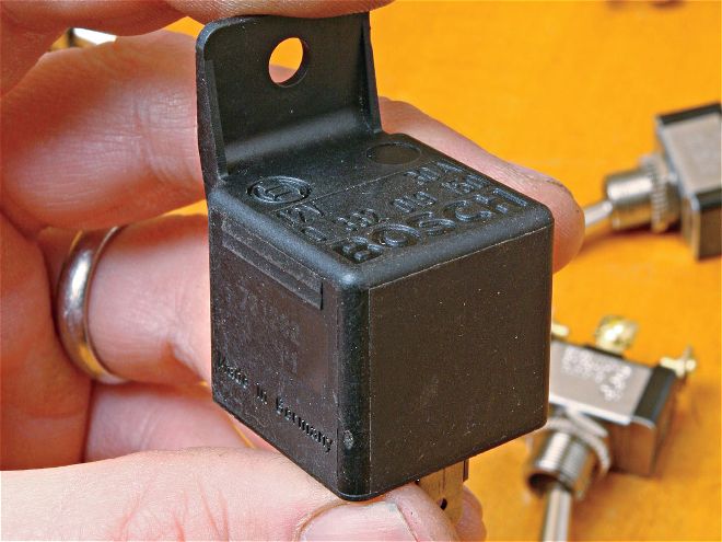
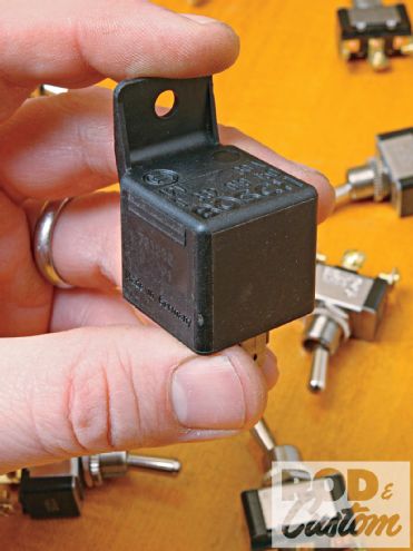
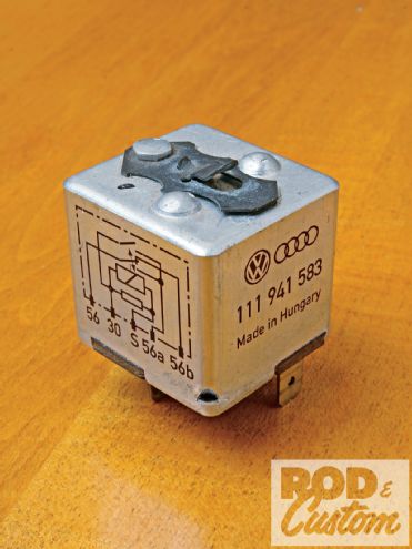 The clever high-beam relay comes in several flavors for Porsche, Audi, Volvo, BMW, and Mercedes-Benz but the most popular and affordable is VW PN 111-941-583. It looks like a regular relay but its terminal pattern doesn't fit universal sockets. Wire it with individual push-on connectors.
To make single-filament, front turn-signal bulbs operate as combination running lights/turn signals, connect the running light or taillight feed from the headlight switch to the front relays' 87a terminals. For a simple dash indicator light, connect one leg of a lamp to constant power and piggyback the other leg to the output side of the flasher module (the side that blinks).
RAP Anyone Can Like
I'm proud that the newest car we own is old enough to vote but a new car once made me jealous. Its radio and power windows remained operational after I removed the key and stayed that way 'til I opened the door.
Retained Accessory Power (RAP) made me actually consider financing a new car. Then I discovered www.the12volt.com, an automotive electrical site chock full of neat tricks and solutions. It has a relay network that recreates the RAP feature with three relays, two $0.50 1N5402 diodes, and door switches that are probably already in your car.
The RAP relays require power from the accessory circuit and common door pin switches. The ones that trigger your dome or courtesy lights will work fine.
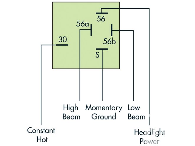 Connect terminal 56 to the headlight switch. Connect terminal S to ground through a momentary switch. When wired this way you can flash the high beams even when the headlights are off.
The system can be configured entirely with SPDT relays but its power will be limited to about 10 amps (which is still respectable). To increase its power, swap the first relay with a high-current SPST relay and you can probably power the entire accessory circuit if you wish.
The system energizes when the ignition switch reaches the accessory position. The accessories will stay on as long as the ignition is on regardless of door position. But as soon as the ignition turns off the accessories will stay on only until a door opens. Turning the key back to the accessory position (or starting the car) will re-energize the circuit and repeat the cycle.
One-Touch Headlight Dimmer
Some of the German cars I grew up with had dimmer switches that operated much like GM switches: pull back once to activate the high beams; pull back again to go back to low beams. The Krauts' system differed in one novel way, though: rather than use a clunky mechanical switch that won't adapt to anything else, they used a relay that can be activated by any momentary switch.
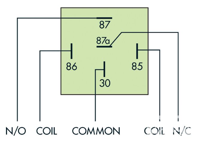 Most relay coils don't care which end gets power or ground but ones with diodes do so make a habit of using 86 as the coil power in and 85 as ground. Either and/or both side(s) may be switched. Terminal 30 is common, meaning that it can contact either 87 or 87a (if a SPDT relay). When the relay is in its neutral state, normally closed (NC) indicates a completed circuit with 30 (as in 87a); normally open (NO) indicates an open circuit (as in 87).
As soon as I figured out how to use those relays I went about replacing floor dimmers with them and retrofitting turn signal stalks with tiny hidden grounding switches. Technically this relay doesn't fall within the definition of universal but it's just too good to ignore.
A quick reminder about terminal S: It works by grounding momentarily. Grounding it for more than a few seconds will overheat and possibly fry it. As a belts-and-suspenders type of insurance, consider splitting each output (56a and 56b) into two wires and route each leg through its own fuse. That will eliminate the likelihood of losing both headlights or beams if a problem arises in one circuit. Painless Performance carries a few stand-alone four-fuse panels, including the very affordable four-circuit ATO fuse center (PN 30002).