
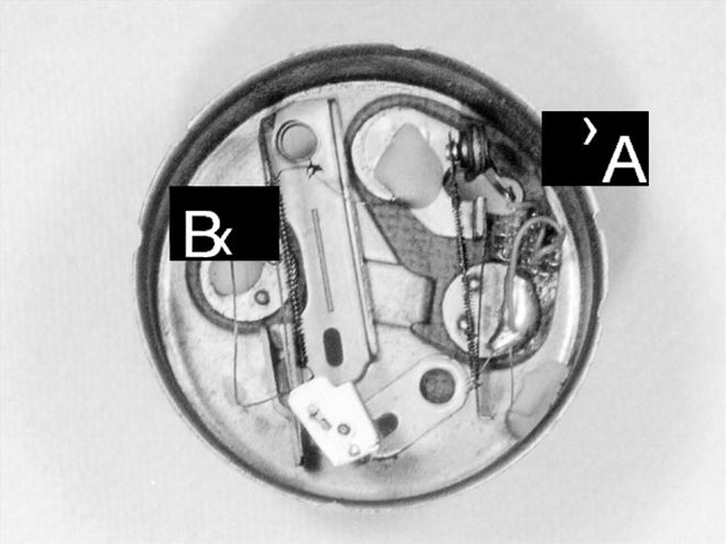
 This '69 Barracuda gas gauge has a built-in voltage regulator (A). When the bi-metal bar (B) is heated by current flowing through the coiled wire, it moves, and the needle moves with it.
Nothing's more frustrating than not being able to rely on the information shown on your car's gauges. Instead of relying on the five gallon gas can in the trunk, wouldn't it be nice to know how to fix the bad gauges?
We'll begin with a look at the instrument panel. If the gauges don't work, is it a bad gauge or sending unit, or a wiring problem? Of almost equal importance is the proper function of the dash lights-brake warning, turn signals, and gauge lights.
The gas, oil, and temperature gauges in our Mopars have a bi-metal bar with a heating element coiled around it that slowly moves the needle. The sending unit (frequently called a switch) consists of either a variable-resistance conductor (temp sending unit) or a rheostat (oil-pressure and gas-level sending unit) and influences the amount of current flowing through it to the ground. Bi-metal-gauge sending units offer less resistance when the engine is cold, gas level is low, or oil pressure is low, and more resistance in the opposite case. More resistance in the sending unit means more current flowing through the gauge's coiled heating element, and thus more movement in the bi-metal bar and the needle. The amp gauge works on the principle of current flow causing a magnetic field, and varying amounts of current/magnetism result in left and right needle movement.
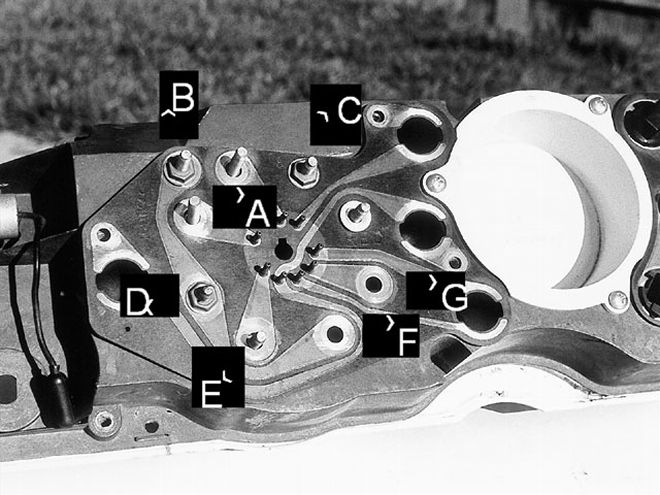 This IC panel shows how power flows through the three-gauge gas, oil, and temp circuit. Terminal "A" is Power In to the gas gauge voltage regulator, then to the gas gauge bi-metal bar in "B." "B" feeds power to "D" (Power In to the temp gauge) and "F" (Power In to the oil pressure gauge). Power flows through each gauge and to the sending unit through the sending-unit terminal. "C" represents the gas-gauge sending-unit terminal. The temp gauge is "E" and the oil-pressure gauge is "G."
Understanding how the gauges work and how the circuit is wired makes it easier to diagnose a problem. The gas, oil pressure, and temperature gauges form a three-gauge circuit, while the amp gauge operates independently.
In a 'Cuda, power for the three-gauge circuit enters the gas gauge's third terminal (the other gauges have only two terminals), where it passes through the built-in instrument voltage regulator, and is passed to the "Power In" terminals of all three gauges. Each gauge has a "Power In" terminal and a "to the sending unit" terminal on the back. You can see from the Integrated Circuit (IC) panel how the power flows through the gauges and to the sending units.
Where To Start and How To Test
Let's say the temperature gauge doesn't work. First, never overlook the obvious. Is the thermostat stuck open? Assuming the engine warms up properly, move on to the diagnostic process. After checking the fuses, start at the sending unit. The diagnostic sequence is quite simple, but it requires an assistant sitting in the car. Disconnect the temperature-sensor wire from the temperature sensor, ground the alligator-clip end of your circuit tester, and have your assistant turn the ignition switch to the "on" position. The temperature-sensor wire should be "hot" (electricity flowing through it). Briefly touch the inside of the terminal with the tester's probe end; if the tester lights up, the circuit is good, meaning no wires are broken. If you hold it a little longer, the needle should move slowly, indicating the gauge is good. Once you see needle movement, stop the test. The light-bulb filament in your tester should allow enough current flow to move the needle, but not enough to damage the gas gauge's voltage regulator during brief tests.
If the needle doesn't move, test the gauge by grounding the wire terminal using the alligator-clip jump wires. Ground the wire very briefly at first. Then, if necessary, ground it a little longer. However, use caution: Directly grounding the sending-unit wires for extended periods can burn out the gauge's circuit and/or the gas-gauge voltage regulator. If the gauge works, the sending unit is bad. (Many late-model cars utilize magnetic-type gauges that move quickly to their positions. Even briefly grounding these types of gauges will damage them.)
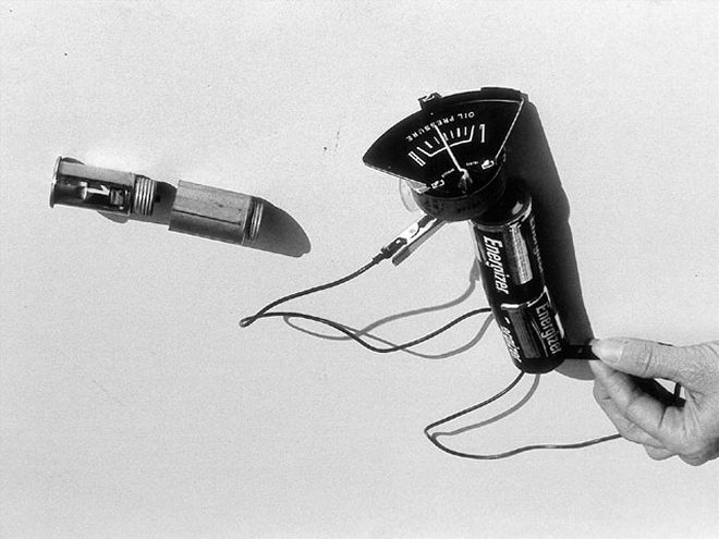 With two flashlight batteries in series (3 volts), the gauge reads half. In this case, one gauge terminal rests against the battery's negative side, and the jumper wire is between the battery's positive terminal and the gauge's other terminal.
If the circuit is cold and the gauge doesn't work, it's either a bad gauge or bad wiring between the gauge and sending unit. Consult the wiring diagram and look under the dash for loose connections and broken wires. If you can see (and reach) the temperature-gauge terminals, test them both with the circuit tester. With the key on, both should illuminate the tester when briefly touched. If the Power In side is hot and the "to the sending unit" side is cold, there's an internal break in continuity and the gauge is bad. If you can't get to the gauge terminals, continue looking for wiring problems under the dash, then move to the engine compartment. Use the wiring diagram to determine the correct terminals and test the temp-gauge wire at the firewall connector. If no problems are found and the connector tests cold, you can assume the gauge is bad.
If all three gauges simultaneously jump to full/high for a few seconds and then settle back to their original readings, the problem is probably the Instrument Voltage Regulator (IVR). (To upgrade your IVR to modern electronics, see the November 1992 issue of Mopar Muscle.) These separate IVRs should attach to the gas gauge on cars with Rallye Instrument clusters, and beside the speedometer on other models. The IVR has a heated bi-metal bar similar to those found in the gauges. As the bar moves, it forces a set of points open and closed to provide a steady flow of electricity to the gauge. The instruments see it as an average of five volts, what they were designed for. If the contact points stay open too long, you'll see simultaneous low readings, and if they stay closed too long, you'll see simultaneous high readings. If your regulator is built into the gas gauge, you'll probably have to have it professionally repaired.
Testing the gas and oil-pressure gauges requires the same technique with two exceptions. If the gas gauge works when testing/grounding out the sending-unit wire, make sure you have gas before pulling the sending unit. If an oil-pressure gauge tests good but doesn't move with the engine running, there are two ways to determine if it's an oil-pressure problem or a bad sending unit. The best, and cleanest, way to test oil pressure is to remove the oil-pressure sending unit and use a mechanical pressure tester. If you don't have access to one, pull the sending unit and have an assistant turn over the motor with the coil wire disconnected or briefly run the engine. If oil shoots out, the pressure is probably okay and the sending unit is bad. If it just oozes out, you have a serious problem. You can bypass this step and put in a new sending unit, but if it doesn't fix the problem, get out the paper towels.
If you have a bad gauge, pull the instrument panel. Disconnect the positive battery cable and cover the steering column with a towel to protect it from scratches.The whole job is easier if you remove the steering wheel. A shop manual shows how to disconnect and remove everything.
Place the panel face down and remove the plastic light bulb holders and the nuts on the gauge terminals. Take out the Printed Circuit (PC) board and inspect it for cracks. Then remove the back of the panel face and test the gauges. Two flashlight batteries placed end to end (3 volts) moves a good gauge up to about halfway. Three batteries push it to about 100 percent. The terminals on the back of the gas gauge are marked "A," "S," and "I." Test it with the "I" and "S" terminals. If it doesn't work, you can't fix it yourself, but Mike Freeman at D&M Restoration restores to like-new condition.
 A well-grounded circuit tester will illuminate if the temp-sensor wire is hot with the key on. If the wire is hot, the sensor or the gauge is the problem. Grounding out the temp-sensor wire should cause a good gauge to move. If it doesn't, it's probably bad. If the gauge did move, check the sender. Keep groundings brief.
Do some housecleaning by restoring the panel face, instrument needles (we've found a 50/50 blend of flourescent orange and fluorescent red Testors model paint works well), and replace all the light bulbs, even if they work. Get replacement plastic bulb holders at the dealer or the local parts house. Before reinstalling the PC board, lightly scuff any place that needs a good connection (like bulb openings and gauge-terminal openings) with 600-grit sandpaper. Scuff the backsides of the nuts for a good connection when everything is reassembled.
Follow these steps, and you should be able to embark on your next trip with complete confidence in your gauges. And you can leave the gas can at home.
Testing Equipment
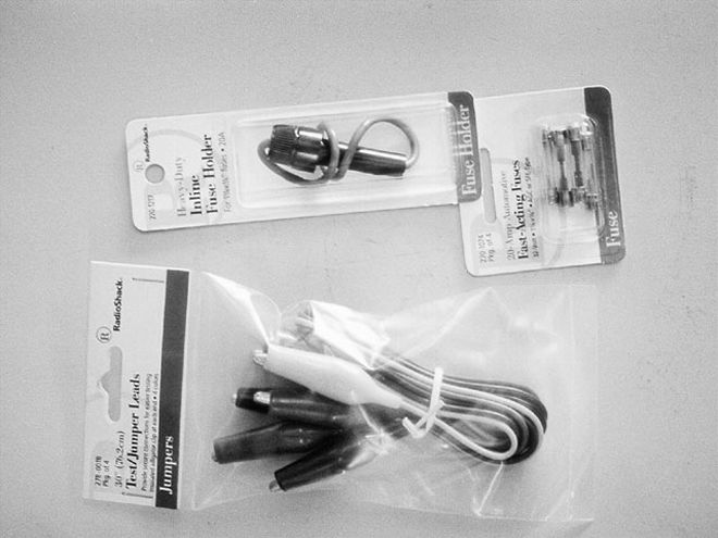
Electrical-testing equipment can be intimidating, but it's really pretty easy to use. In this story, we describe a bucks-down way of testing gauges with three batteries and a length of wire. In this series, we have also made several references to a fused jumper wire.
A jumper wire is used to complete the circuit during testing. Alligator-clipped wires are available at Radio Shack, as are inline fuses. We bought a package of four jumpers, 20-inches long, and spliced a 20-amp inline fuse into the red wire. The cost was under seven bucks.
The best piece of electrical testing equipment is a multi-meter. Lighted-handle-type circuit testers and less expensive testers were common because, until recently, a dedicated multi-meter was pricey and not easily justified for a weekend enthusiast. However, multi-meters have become so affordable there's no reason not to have one. The Craftsman unit pictured here is a capable unit and costs $25-$35. There are more expensive models on the market, but this one suits our needs. We've also seen multi-meters under $15 that are also capable units-but the hard case on this Craftsman unit won us over. If you don't know how to use a multi-meter, Craftsman sells a good book for a few dollars that teaches you how to use one, and Radio Shack has a basic electrical testing book.
When It Doesnt It Work
When something doesn't work, the cause is usually one of six things; no power, an inoperable accessory (or bulb), no ground, a bad switch, a bad relay, or a wiring problem.
The following seven steps, when followed in order, should help you solve just about any electric problem in your car:
Check the power source. Your problem could be a bad battery or a blown fuse. Never overlook the obvious. Check both ends of the fuse with a circuit tester. We've seen fuses that looked OK, but had an internal break in continuity.
Check the accessory (or bulb) itself.
Test for power at the accessory.
Test the ground.
Test the switch(es)
Test the relay (if applicable).
If 1-6 are OK, its time to drag out the wiring diagram and start tracing wires.