Automatic transmissions have made huge advances in performance, but for many drivers nothing beats rowing through the gears manually when they take their favorite Chevy out for a cruise or to the track. Of course, a manual transmission requires a clutch, so the next big decision is if it’s going to be mechanical or hydraulic.
Many people prefer a mechanical clutch because it has a better feel compared to a hydraulic one, but a mechanical clutch sometimes requires adjustment as the clutch wears. Hydraulically actuated clutches tend to self-adjust so long as there’s fluid in the reservoir, and they are often easier to fit into a given space. Ask a group of gearheads what they prefer and you’ll most likely get arguments both in favor of and against each system.
Still, sometimes it’s not possible to run a mechanical clutch because the clutch linkage interferes with other parts under the car, or if the car didn’t originally come with a mechanical clutch system, it’s easier to source and install a hydraulic system.
Buying all the parts for a hydraulic clutch system separately can be problematic since it’s critical that all the components be matched properly. That’s why the best option is to buy a pre-packaged kit from a company like American Powertrain.
American Powertrain’s Hydramax line of hydraulic clutch kits contain components that are volume-matched to each other and designed to work in concert. Their adjustable master cylinder bracket makes it easy to dial in the correct clutch rod angle, which is critical for smooth operation. These kits are offered for vintage four-speed and Richmond transmissions as well as modern units like Tremec T-5, T-56, TKO, and Magnum six-speeds.
Our project is a 1969 Camaro with a Tremec TKO five-speed behind a small-block Chevy engine. The owner didn’t mind the mechanical clutch, but it interfered with the new headers.
Follow along as we go through the steps involved with replacing the mechanical linkage in favor of a fluid solution.
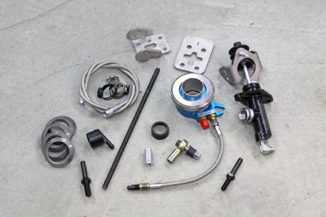
01. The American Powertrain Hydramax hydraulic clutch kit makes replacing your old mechanical linkage system as painless as possible. The kit comes with a bead-blasted stainless firewall mount, volume-matched Wilwood master cylinder, their pre-bled Hydramax concentric internal slave cylinder, reservoir kit, and all the lines, shims, and fittings needed for installation.
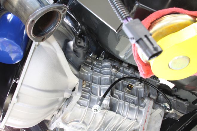
02. Our 1969 Camaro was running a Tremec TKO five-speed transmission with a manual clutch linkage system. The problem we were running into was that the linkage was hitting the headers we wanted to run.
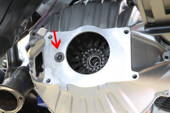
03. The first step was removing the TKO transmission from the car. We left the bellhousing in place so we could get a few critical measurements needed to set up the new Hydramax system. The pivot ball (arrow) needed to be removed from the bellhousing.
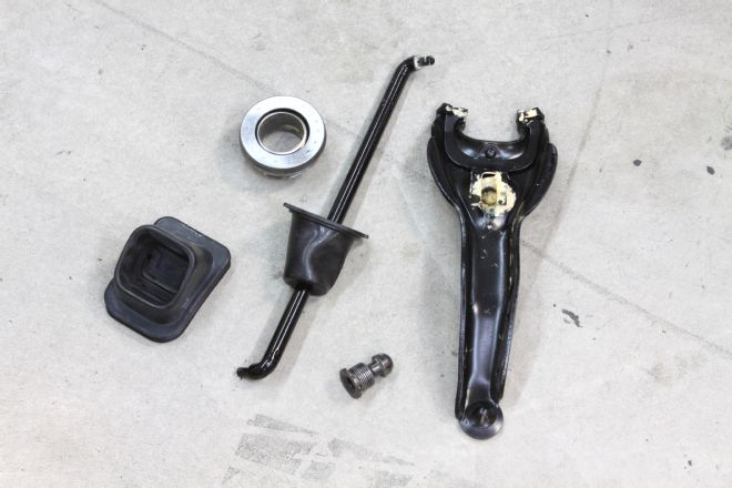
04. Here are most of the parts from the mechanical clutch system we removed from the Camaro. The only one we reused was the square rubber boot seal for the bellhousing.
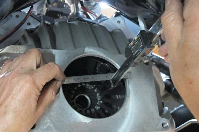
05. The first measurement was the distance (measurement A) from the clutch finger to the mating face of the bellhousing. This came out to 2.860 inches.
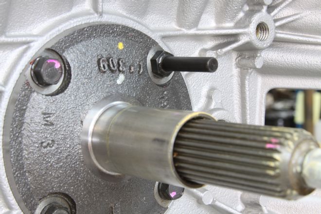
06.. We then replaced the upper right bearing retainer bolt with this retainer stud that came in the kit. A small dab of blue thread locker was used to keep it in place. The hydraulic release bearing (HRB) rides on this during operation.
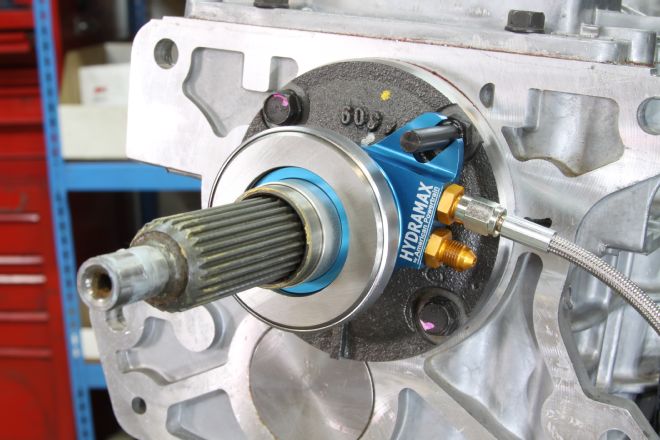
07. With the stud in place, and after wetting the inside of the sleeve with a little brake fluid, we slid on the HRB.
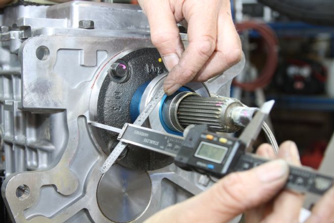
08. We next measured the distance (measurement B) from the HRB face to the transmission face where it would contact the bellhousing. When taking this measurement we pushed in and seated the HRB against the base of the bearing retainer (collapsed). This came out to 2.521 inches.
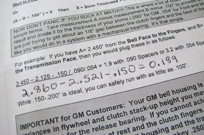
09. OK, time for some fun with math. What you’re shooting for is about a 3/16-inch gap between the clutch fingers and the face of the release bearing. So, measurement A, minus measurement B, minus 0.150 (for an air gap) equals 0.189 inch. According to American Powertrain the ideal number is between 0.150 and 0.200 inch (although you can safely run with as little as 0.100 inch), so we needed to make up about 0.189 with the provided shims. Each shim is worth 0.090. We used two shims, giving us a gap of 0.159 inch, right in the sweet spot according to the instructions.
10. These are the shims we used to make our numbers work out right. When pulling the HRB from the input shaft, we used a small pry bar under the center of the back of the assembly. If the HRB comes apart when removing, it won’t be ruined, but it will need to be re-bled, which is a hassle. If a tall clutch or flywheel leaves you with too little space for the HRB you can shim the bell away from the transmission using small washers (up to a max of 0.200 inch) or buy a ready-to-go 0.250-inch CNC spacer from American Powertrain for about $49.
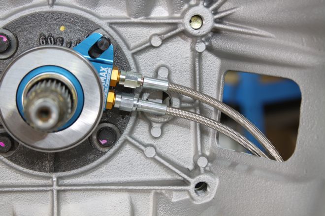
11. We then installed the bellhousing to the transmission and slid the HRB back into place. The bleed line came pre-installed and full of fluid so we didn’t mess with it and just installed the supply line, which will go to the clutch master. Before connecting the other ends of the lines we installed the square boot from the old mechanical clutch linkage to seal up the hole in the bellhousing a bit.
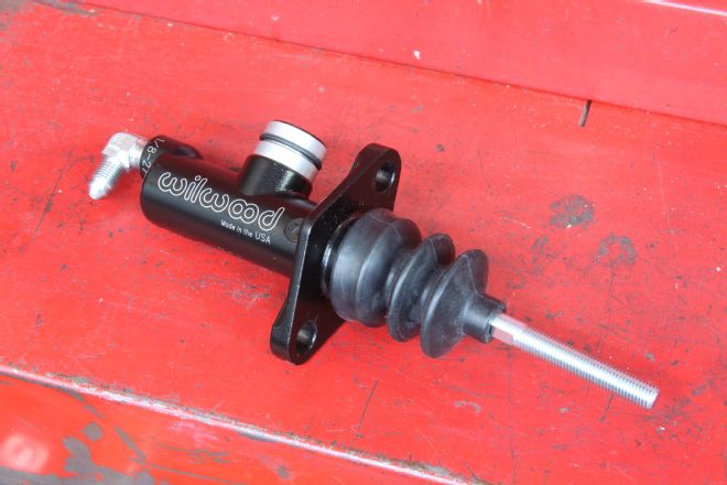
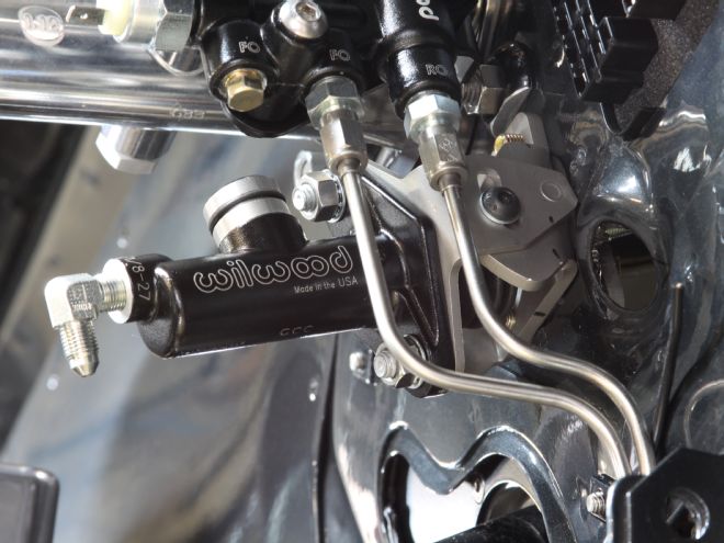
12. This volume-matched Wilwood master cylinder came with the kit. You can use any DOT 3 non-silicone brake fluid with the system, but they recommend high-temp racing grade fluid to reduce heat absorption.
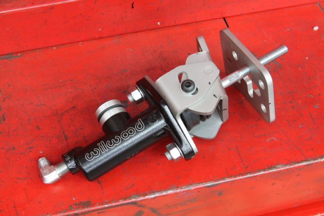
13. This gives you a good idea of how the Hydramax-2 adjustable firewall mount goes together. It’s corrosion-free, bead-blasted stainless steel, and allowed us to dial in the right pushrod angle from the master to the clutch pedal. The backing plate goes on the inside to the firewall and clamps the assembly in place, reducing firewall flex.
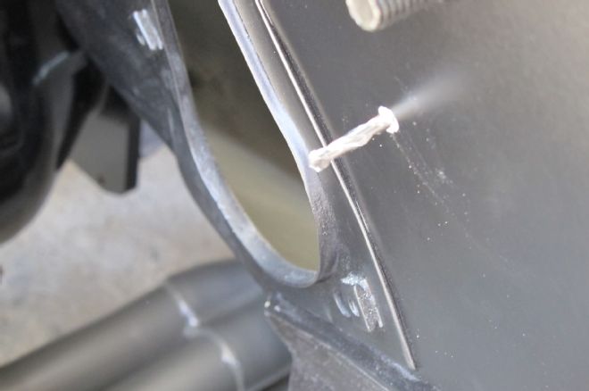
14. Most cars, ours included, will have an existing hole in the firewall perfect for the clutch master. It should be located just below and slightly to the right of the brake master. If not, you will have to drill a hole large enough for the clutch master rod to pass through. If you need to do this, make a pilot hole then work your way up.
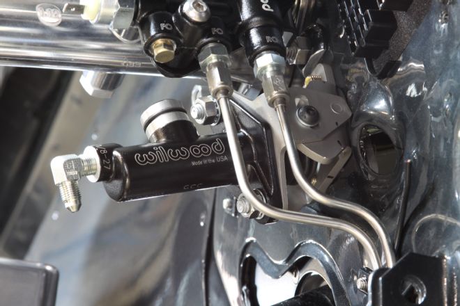
15. And here’s what the master and bracket looked like when mounted to the firewall. The outer bracket is threaded to accept 5/16-inch bolts from the inside of the car (through the backing plate). There are four holes, but only three are required to be used.
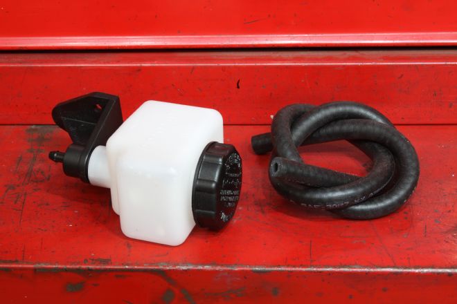
16. The master cylinder kit came with this plastic reservoir kit, but they do offer a billet version. The reservoir can mount anywhere so long as it is higher than the HRB to allow for bleeding. Once bled, it can be placed below the HRB if desired.
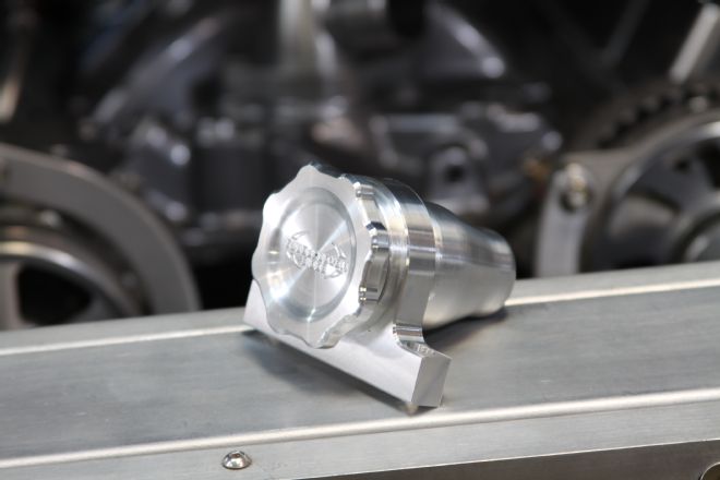
17. This car is an Eddie Motorsports project so they wanted to utilize their new billet reservoir. It’s pretty and serves the same function as the plastic one that came in the kit.
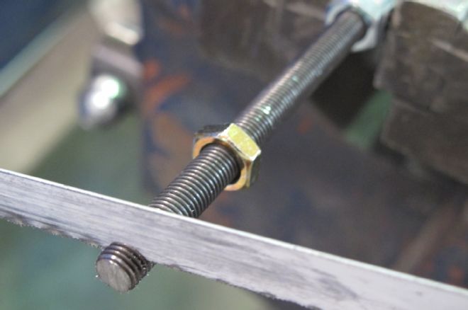
18. After doing some measuring, we found we needed to cut a bit off the threaded clutch pushrod. The firewall bracket is self-aligning, ensuring that the pushrod angle is the same as the clutch master so that when the pedal is depressed the rod pushes straight into the master. Any angle on this rod will cause clutch master issues down the line.
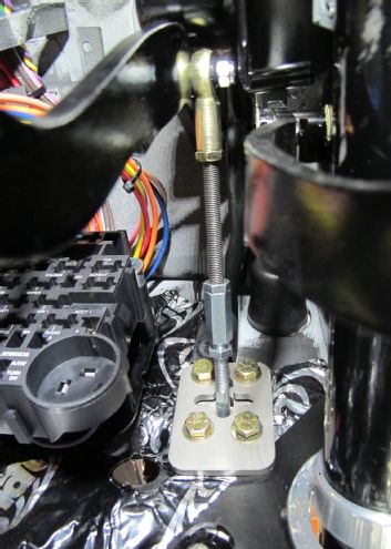
19. Here’s how the rod assembly ended up. The spherical Heim joint attached to the clutch pedal using the provided hardware and the threaded rod went from it to the turnbuckle nut on the clutch master’s pushrod. When adjusting the rod, the master cylinder rod must come all the way up as far as it can (home position) when the clutch pedal is at rest. If the rod remains partially depressed when the clutch pedal is at rest, the one-way valve in the master will suck in air every time the clutch pedal is depressed, making bleeding impossible. Because the Hydramax HRB is pre-bled, bleeding the system generally requires nothing more than pumping the clutch pedal until the air has worked its way out of the system.
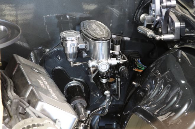
20. And here’s the complete system installed and plumbed to the transmission and billet reservoir. We wanted to make sure we didn’t over-stroke the release bearing (bottoming out the clutch fingers). If this happens, the fingers can deform or could blow the seals out of the release bearing. To prevent this, we adjusted (per the American Powertrain instructions) the provided jam nuts on the master cylinder pushrod to limit its travel then followed the bleeding instructions. And with that, the project was finished and we could complete our exhaust system.