When putting your car together for a new season, or building a new car from scratch, you need to consider the driveline alignment when mounting the engine and rearend. Because this is one of the basic design features of the car, it can and must be done initially to save a lot of work later on moving things around.
There is now a good deal of information about driveshaft technology and geometry that we have available. Most of this technology has been developed for production cars, but racing applications require a closer look and slightly different approach to this information. The advantages of this knowledge are in the area of reduced power loss and increased component life. The bulk of this information was furnished to CT by Barry Zackrisson. To begin with, we need to know what to call the various components related to our driveshaft.
 The driveline in our race cars include the transmission shaft, the driveshaft, and the pinion shaft. All of these need to be in alignment and made to withstand the stress of racing. We’ll tell you how to do that.
Driveline Terminology
The component names for the driveline parts are as follows:
Slip Yoke—this is the yoke at the front of the driveshaft that goes into the transmission and can slip to take up the slack of chassis movement.
Weld Yoke—is the yoke at the each end of the driveshaft that attaches to the pinion yoke at the rearend and the Slip yoke at the front. These are welded to the shaft tubing.
Universal Joint Kit or U-Joint (UJ)—is the actual part that forms the rotational connection between the driveshaft and the transmission and rearend.
Tubing—is the metal tubing between the weld yokes.
Pinion Yoke—is the yoke that is attached to the pinion shaft at the rearend.
Driveline Angles—When the UJ operates with any amount of driveline angles, this creates a problem. The bearings speed up and slow down twice per revolution of the driveshaft. This causes an oscillation in the powertrain. The more angles that we have, the higher the peaks of oscillation we see and therefore the greater chance of vibration.
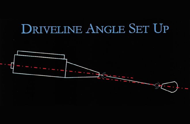
Driveline angles are a cause of vibration and power loss. If your race car must have driveline angles from a design standpoint, the angle of the driveshaft to both the transmission output shaft and the pinion shaft should be equal and also opposite. The angle should also be kept to a minimum when at all possible.
Driveshaft angles are not only measured from a side view, but also from a top view. Some offset Late Model cars can have as much as a 11/2 inch displacement of the rear of the driveshaft from the front. That equals almost 2 degrees of driveshaft angle at both the transmission and the pinion. So, we can align the driveshaft, from a side view, to zero angle and still have 2 degrees of driveshaft angle present.
The latest recommendation might come as somewhat of a shock to most racers, but strictly for racing applications, Zero Driveshaft Angles are encouraged. That's right, based on recent studies and testing, a race car with zero driveshaft angles at the transmission and pinion will not harm the U-joint bearings. The natural vibrations that are produced by the race car will cause the U-joint bearings to rotate enough to stay lubricated and not flat-spot.
In the real world, the driveshaft will never really maintain a zero angle configuration through the diving and rolling of the chassis as we lap the track. Starting at zero means that we will stay very close to zero at all times. For extreme applications, such as when racing at more than 180 mph at Daytona or a similar type of track, the teams will align the drivetrain for zero angles with the car placed at the on-track race attitude.
NOTE: For overall consideration in driveline angle design, number one is to keep the driveline angles as low as possible and keep the angles equal and opposite at each end of the driveshaft.
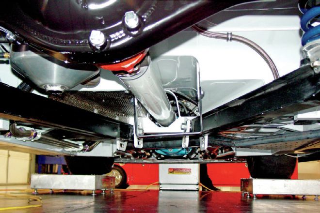
 Driveshaft alignment is critical to reducing power loss and vibrations that can kill components. Basically the tranny output shaft and the pinion shaft need to be parallel to one another and the angles they make with the driveshaft need to be opposite. Modern race cars can have near zero pinion and tranny angles to the driveshaft.
Controlling Driveline Vibration
The sources of vibration in our racing driveline, in order of importance—most critical at the top, are:
1) Run-out
2) Improper driveline angles
3) Looseness in the fit of any of the parts
4) Unbalanced parts
5) Component deflection
6) Reaching critical speed
We will examine some of these causes and see how we can cure many of them just by using better parts that are designed for the racing environment.
 This fixture checks for yoke run-out. To reduce vibrations in the driveline, all of the components need to be straight and wobble free.
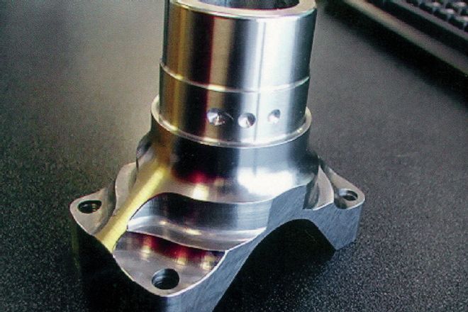 This Cup-style yoke has been drilled for balancing. This is obviously more important for higher RPM ranges, but the life of your U-joint bearings and pinion bushings will be longer when you have everything balanced.
Yoke Design
The only attachment design for holding the U-joints that is suitable for all out racing is the strap design. The U-bolt attachment that is commonly used on passenger cars and trucks is no longer considered acceptable for several reasons. One reason is that it has less strength than the strap design; two, it may distort the bearing caps if over-torqued; and three, it grips the cap at three points whereas the strap design grips it in four places, which translates to less distortion of the caps.
U-Joint Kit Designs
There are basically two designs of U-joints available. The popular standard zerk designs is used for production vehicles and has, as is obvious, a grease zerk for lubrication. Inherent in this design are hollow shafts that provide the means for the grease to reach the bearings. This hollow design also makes the part weaker than if it were solid.
The other design is called the Sealed Design, or Solid U-joint and has no grease fitting and therefore a solid core. This unit has precision seals that keep the lubricant with the bearings while also sealing out dirt. The sealed design is therefore much stronger.
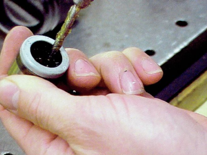
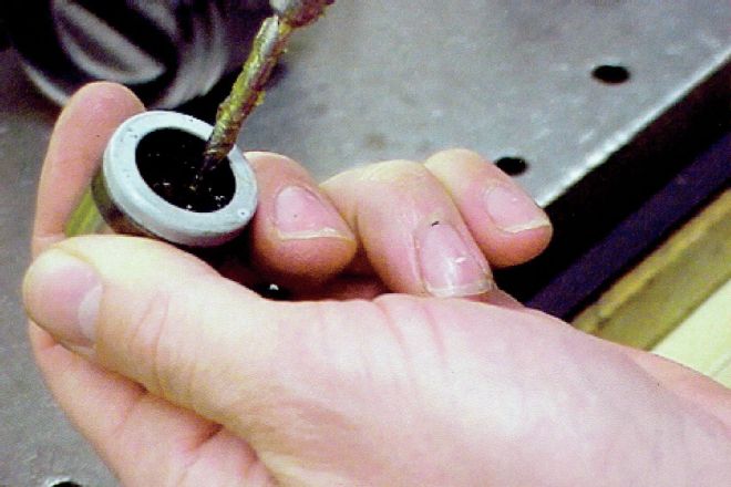 When greasing the needle bearings in the U-joint caps, spread the grease to cover all of the bearings, but don’t apply too much. If you do, when you press the caps over the shaft, you’ll blow out the seals.
Proper lubrication of the sealed U-joint is simple, but can be overdone. We always want to coat the bearings, but not excessively. We also need to fill the trunnion cavity with grease, but not overfill. If too much grease is applied, then when we attach the caps, the pressure from the grease trying to escape will literally blow out the seals and ruin them.
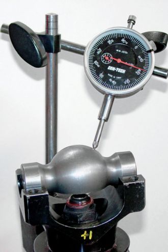
Adjusting Run-out at the Pinion Yoke
A major cause of driveline vibrations is when the pinion yoke has a measurable degree of run-out. We can test the run-out after the installation of the U-joint in the pinion yoke by using a dial indicator that is attached to the rearend housing.
We measure at both sides of the U-joint and then if the offset is different, we must remove the pinion yoke and rotate it on the pinion shaft to find a position that will index more correctly. This is a very important and necessary step in reducing driveline vibration.
Failure Mode—Fatigue Crack Propagation
Driveline components can fail due to a number of reasons. Cracks in the welded yoke or driveshaft will accelerate the failure of your driveline system.
Cracks can occur from the stress of an already weak part or upon construction of the parts due to the heat of welding. We recommend welding any driveline part using the TIG welding technique instead of MIG welding.
Balancing the Drive Assembly
The only true way to balance a driveshaft is through the use of a Two Plane balancer, or one that simultaneously balances both ends and has the capability to Cross Talk between ends. This allows the equipment to derive a dynamic model of the forces of the imbalance to determine the force vectors involved and formulate a solution that takes into account both end's influence in the overall balance of the shaft.
A simple automotive driveshaft balancer is fine for grandma's car, but for racing, with the very high rpm we experience, we need more precision.
Snap Ring Failure
A common failure in our racing driveline is when the retainer snap rings come out of the yoke. There is a simple and easy way to reduce this occurrence by applying a spot of epoxy to the ring. This prevents the ring from collapsing and falling out of the ring groove.
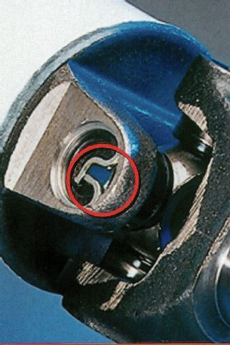 A trick to prevent the snap ring from coming out is to apply epoxy to the inside of the part where the two ends of the ring come together. This prevents the ends from closing together and allowing the ring to come out.
Conclusion
The important things to remember are to use driveline parts that are made specifically for racing when possible. Make sure you install the components correctly to reduce driveline vibrations and parts failures.
Check the alignment of your system and correct any misalignment. When buying the driveshaft, make certain it is up to the task for the intended rpm range you will be running in your type of racing. Periodically check driveline parts for cracks or for signs of a bent or dented shaft.
The professional teams that run the top series in NASCAR always use new driveline parts for each race. We don't necessarily need to do that at the short track level, but knowing they do that says something about the importance those teams place on the driveline components. That same concern should be shared by all racers.