As pointed out last month during our foray with motor mounts (I do realize that "engine" is the correct term, but "motor mounts" just sounds better!), we opted to push the steering off till we received the parts I should've ensured we had in the first place—that being the heavy-drop steering arms. Initially, I'd figured we could set the box and linkage up with the 1 3/4-inch dropped arms on hand, then simply swap arms out later. I simply thought wrong. Not only does the additional 2-inch drop in the steering arms locate the tie rod below the wishbones, it ultimately dictates where the drag link, Pitman arm, and of course the steering box itself are located/mounted.
For the Borgeson Universal Company Vega box itself, Jimmy White chose to use a framerail bracket/mount design of his own—one which utilizes a basic lower brace with integrated threaded bungs along with a through-frame threaded mount. This allows for plenty of options locating and positioning the box, and in a structurally bulletproof manner (the upper mount virtually eliminates any possibility of stress fracture). So, with the heavy-drop steering arms installed, the remainder of the chassis' steering could now be tackled; we'll tend to the upper echelon components (column and intermediate linkage) once we're further along with the body.
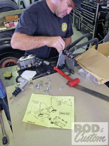
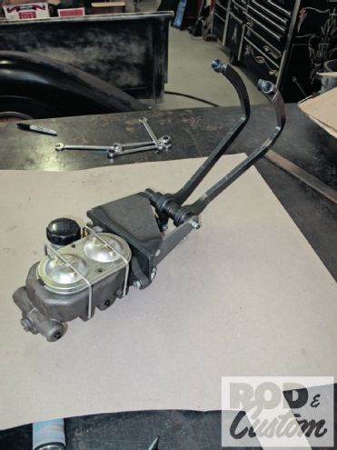
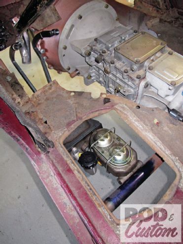
Fortunately, there weren't any issues with the pedals, as I'd left the details up to my pal Jason Slover at Pete & Jake's to handle—suffice it to say, he came through with flying colors, as expected. All we had to do was roughly assemble the kit, which was supplied with a manual dual-reservoir brake master and hydraulic clutch master cylinder, and reference the supplied directions before installing the unit onto the '33. Obviously, the hard(er) part will come when we're faced with hooking up the clutch—for now, I'm more than content checking the pedal assembly off the "to do" list.
1. We sourced the sedan's pedal assembly from Pete & Jake's (PN 4040). The '33-34 kit includes your standard fare GM dual brake and Wilwood hydraulic masters (with pedal linkage), pedal assembly, weld-on frame bracket, and good old-fashioned, hand-drawn illustration, just the way it should be!
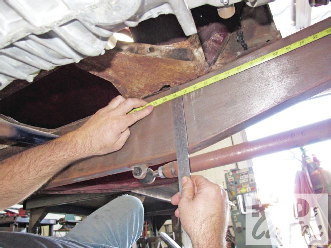
2. With the pedal kit pre-assembled, locating ensued, which the aforementioned illustration (and of course a straightedge and tape) greatly aided with.
3. Our starting point was taken approximately 37 inches back from the front crossmember, that, combined with the width of the bracket itself, gave us our parallels and perpendiculars for which to mark the framerail accordingly.
4. With a little assistance from above (Omar kindly held the assembly in position while I took the photo), White tack-welded the bracket in place.
5. Pete & Jake's indicates positioning the top of the mount 1 3/4 inches below the upper framerail edge for proper floor clearance; the angle is dependent on the stance dictated by the front suspension.
6. A "stock" '37 Ford column/mount (hung off the dash's factory holes) not only navigates between the pedals perfectly but clears the Hedman Husler header that, up until this point, I was on the fence about using. Looks like the only thing I'm uncertain about now is the steering column—but seeing as the steering wheel itself has already been chosen (a cut-down original Crestliner), chances are you'll be seeing an aftermarket unit in the future.
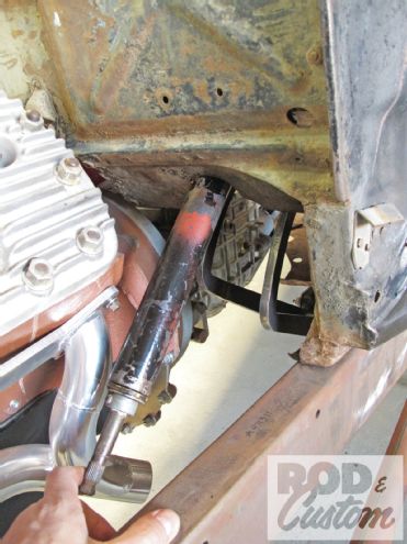
7. As it turned out, that 37 inches put our master cylinder in close proximity to the tranny crossmember—close, but not to the point of interfering. Needless to say, had there been any clearance issues, we would've resolved the issues with a smaller master cylinder. Nice that Henry already accommodated my fluid servicing needs with a built-in access door!
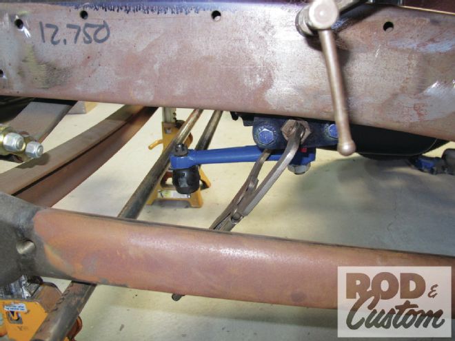
8. OK, with the pedal assembly segment out of the way, we were able to move forward with the steering, starting with the 3 3/4-inch dropped arms provided by Speedway. The standard 1 3/4-inch arms allowed the tie rod to clear above the wishbones, however, not without posing clearance issues with the frame, and notching the 'rails was not a preferred option.
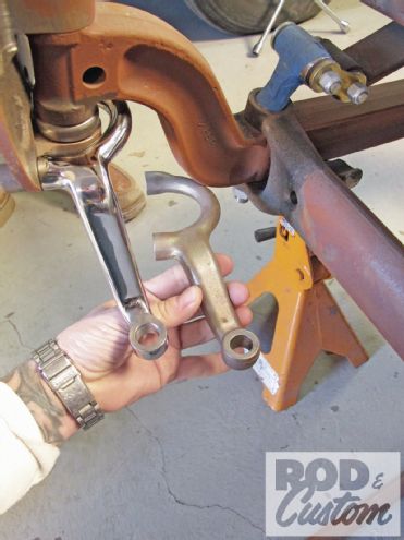
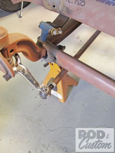
9. The additional 2 inches of drop in arm length allowed the tie rod to mount below the wishbones, eliminating all clearance issues (without having the tie-rod ends or Pitman arm surpass the scrub line either).
10. Before installing the box and drag link, we set the toe-in roughly an 1/8 inch.
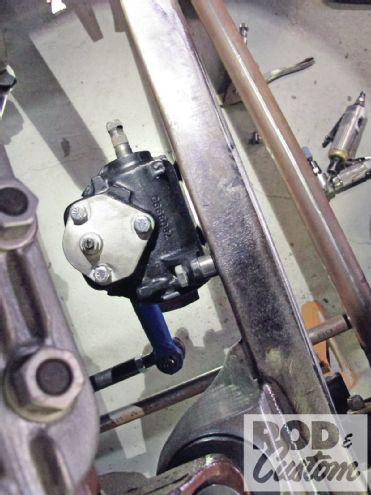
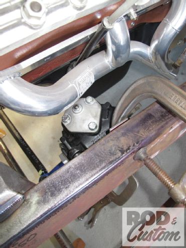
11. For as long as I can recall, Vega cross steer has been the setup of choice for the majority of solid-axle hot rods—it simply works, very well, affording plenty of room for exhaust and other chassis-related items that other steering boxes don't. In our case, we're using a tried-and-true Borgeson Vega box mounted via a CCHR bracket.
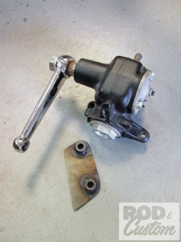
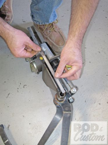
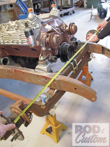
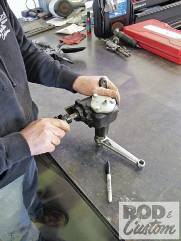
12. The box itself was centered prior to being hung—a Sharpie, 36-spline joint, and the Pitman arm are all that's required for this step (four-and-a-half turns divided in half!).
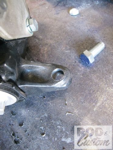
13. Also, the Vega's cast mounting flanges are pre-tapped 3/8 inch; for our application, the upper ear, however, was drilled out to 7/16 since we're using a through bolt attaching the box directly to the framerail, as you're about to see.
14. White's Vega bracket allows the angle in which it's mounted to be adjusted per application simply by trimming the edge to suit. An additional gusset will be added to further strengthen the mount.
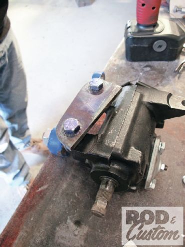
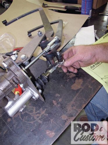
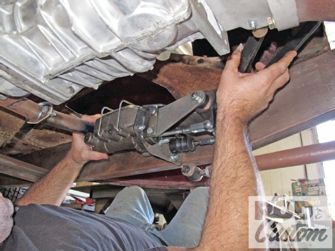
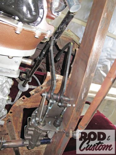
15. With the drag link attached, it's a bit cumbersome mocking up the Vega box and bracket, so White fashioned up a nifty "jig" of sorts using a couple clamps and scrap metal to act as his third (and fourth) hands prior to drilling/welding.
16. With the box jigged up onto the framerail, the drag link was positioned to run fairly parallel to the tie rod, with the Pitman set at a slight downward angle (as shown).
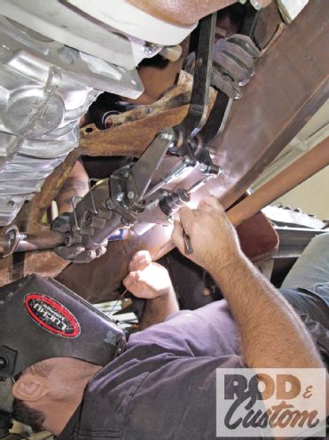
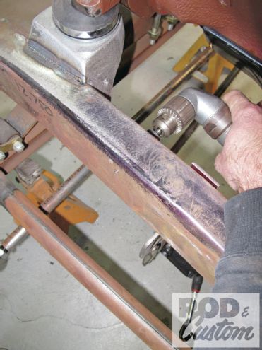
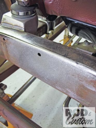
17. A transfer punch was used to mark the location for the box's upper mount onto the 'rail. With the engine in place and little room to work with, a pneumatic angle drill had to be used.
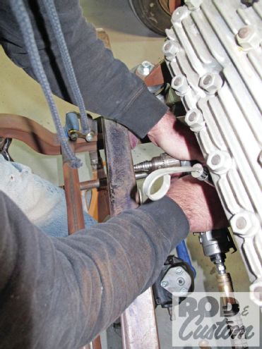
18. While the above-mentioned drill accommodated the space constraints for the initial drilling, there was still the second outer hole to be drilled. For that, White came up with this "device" to align the bit when drilling the pilot from the backside.
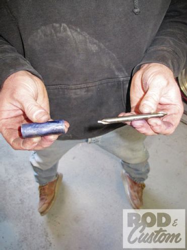
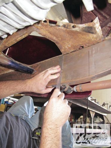
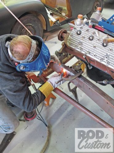
19. Rather than simply weld a bung flush to the boxed section of the framerail for the upper mount, we chose to use a full-length piece of tubing to avoid any worries of stress fractures. The tubing is tapped (7/16-20) roughly 3/4 in, the outside end left solid.
20. Once positioned with the box and linkage in place, the bung is fully welded to the outside of the frame, then finished off, leaving no evidence of its existence. The perimeter of the inside is also fully TIG welded.
21. Now all that remains as far as the steering goes is choosing, installing, and linking up a column.