Like many of the trucks seen in Custom Classic Trucks, our F-1 has undergone suspension modifications and the original I-beam and worm-and-sector steering gear were given the heave-ho in favor of a Mustang II IFS and rack-and-pinion. While the suspension and steering installation were satisfactory, the same couldn't be said for the steering column-the recycled Mercury column was not only ugly, but it was too close to the driver door and, worst of all, the U-joints were of questionable health, weren't phased properly and had been welded to the intermediate shaft. To make things right it meant starting all over.
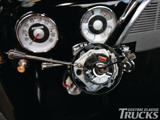
 We updated our F-1 with a new Flaming River tilt steering column equipped with an ignition switch and shifter. It’s topped by a Flaming River leather-wrapped steering wheel. The original instruments were restored and updated to 12 volts by Williamson’s Instrument Repair.
When installing a column, the first concern is usually positioning the wheel at a comfortable angle. In many cases a tilt column can help with that, but while the angle of the wheel from vertical is important, where the column points on the horizontal plane is often overlooked. One of the design elements often found on many high-performance vehicles is that the steering column is at a very slight angle that follows the driver's line of sight to the center of the lane in front of the vehicle. While it may seem unimportant, driving a truck in which the steering column points noticeably to the left or right from your normal line of sight can be disconcerting, even if you don't know why.
At one time, steering column changes required some scrounging-it wasn't unusual to use industrial U-joints or those adapted from a donor car (Porsche and Tornado U-joints were once popular). Fortunately, today there are quality components readily available for reasonable prices, like those we used from Flaming River. In most truck installations with conventional steering there will be at least one U-joint, IFS often requires two and in some cases three or more. Installation procedures have also changed, pinning or welding U-joints was common practice, and while those are still common practices with race cars, neither are necessary, or suggested, for street applications, Today, U-joints and shafts with double-D or splines make the connection easy and safe-double-Ds are easy to cut to any length and assemble, while splined shafts come in various lengths (and may usually be shortened an inch on each end) to provide finer adjustments for positioning the steering wheel-the important point is that both designs are absolutely safe and reliable when installed according to the manufacturer's guidelines.
When replacing the steering column, U-joints, and shaft in our truck we chose to include some flexibility in the system. As we see it, the steering column is solidly attached to the body and the steering gear is bolted to the front crossmember of the frame so some flex between the two is needed. By including a slip-shaft between the column and the steering gear any movement will be absorbed by the slip-shaft rather than transferring the stress and strain to the U-joints. New cars have them as a means of absorbing movement between the body and chassis, so we figured our old truck should too. There are several methods to do this, we opted for an EZ shaft kit as it has a hex shaft for the ultimate in strength and includes three inches of up-and-down movement to absorb chassis flex and will collapse in the event of a collision. Flaming River can supply an EZ Fit shaft for any two-U-joint system-just specify the length, column, and box size.
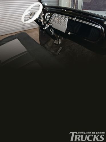
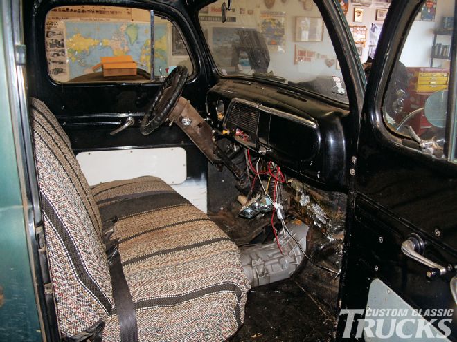 It's hard to believe this is what we started with, but it just goes to prove you can make a silk purse out of a pig of a pickup.
There are several methods of mocking up new steering shafts, we've used welding rod for simple installations-PVC pipe and wood dowels also work well. Keep in mind, if more than two U-joints are used, a support bearing will be required-and a double U-joint is considered two, so a single at one end of a shaft and a double at the other requires a support bearing.
Replacing the steering column in our F-1 with a new powdercoated tilt unit from Flaming River not only improved the truck's appearance, the column-mounted shifter and dimmer switch at the end of the turn signal lever are much more conveniently located than before. Less obvious is that the steering wheel is now in a more comfortable position as the column has been moved away from the door with a new column drop and floor mount, also from Flaming River. All these changes make the truck much more comfortable to drive. Less obvious, but every bit as important from a safety standpoint, are the new U-joints and slip-shaft. Now every turn is a good turn with our F-1.
Here are tips from Flaming River on installing universal joints and shafts:
Universal Joint Installation
1) Measure and mark 7/8 inch in from the end of the steering shaft.
2) Position the yoke onto shaft up to the 7/8-inch mark. Tighten the set screws to mark the shaft.
3) Remove the yoke.
4) Using a 1/4-inch drill bit, countersink the marked position on the shaft.
5) Apply red thread locker to the threads of the set screws.
6) Reinstall the universal joint onto the shaft.
7) Using a torque wrench, tighten the set screws to no more than 25 ft-lb.
8) Tighten the jam nuts.
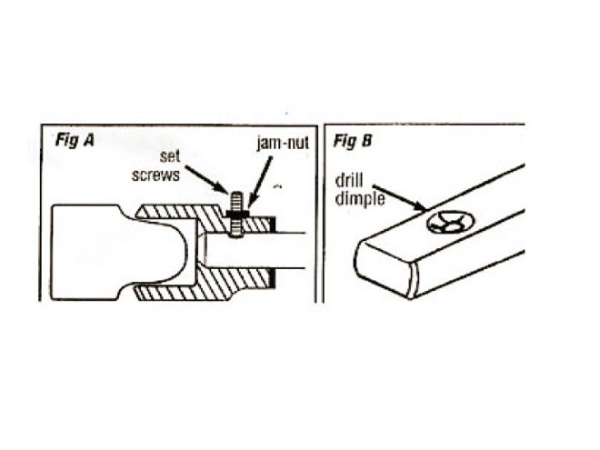 This drawing shows the location of the "dimple" and how the shaft should be inserted so as not to protrude past the end of the U-joint's yoke.
Shaft Installation
1) Measure and mark 7/8 inch in from each end of the DD-style shaft.
2) Slide the splined U-joint yoke over the pinion shaft of the steering gear
.
3) Insert the DD-style shaft onto opposite end of the U-joint.
4) Slide the DD U-joint over the shaft.
5) Apply red thread locker to the screws.
6) Insert the tongue into the end of the steering column shaft and install the through bolt. (Do not tighten the bolt at this time.)
7) Adjust each U-joint to align with the 7/8-inch mark on the shaft. This ensures proper phasing. Be certain the set screw on the steering gear end is set in the groove in the gear's shaft.
8) Snug each set screw so it will leave a mark on the DD shaft, to include the tongue.
9) Remove the shaft kit and dimple each set screw mark using a 1/4-inch drill bit.
10) Reassemble the shaft kit in the cab. Tighten each set screw with a torque wrench to 25 ft-lb. Tighten the jam nuts. (Note: Periodic inspection of the set screws is recommended to ensure that they stay tight.)
Flaming River FAQs
Common Steering Column Installation Errors
Incorrect Column Angle-When the column angle going through the firewall or the floorboard is not taken into consideration it can affect the entire steering system.
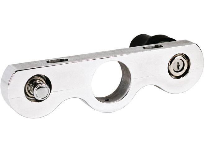 Another option is this billet mount that includes an ignition switch and power outlet.
The biggest effect will be in the U-joints and shafting. With the column being at angle it can cause an extreme angle in the U-joint causing a bind and turn a relatively easy two-U-joint system into a three- or possibly a complex four-U-joint arrangement.
Inside the vehicle the incorrect column angle can affect driver comfort by having to always adjust the tilt in the column or in extreme cases driving with their arms almost fully extended.
Incorrect Column Length
Getting the correct length steering column can make or break the way a truck feels. Having a column that is too long can affect driver comfort and make them feel cramped or crowded while driving. If it is too long and goes through the firewall too far it can cause a binding in the U-joints.
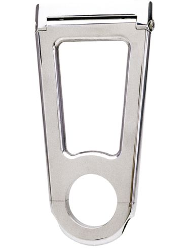
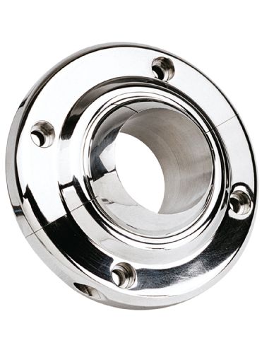 This billet aluminum ball-and-collar swivel design floor mount simplifies column installation by allowing up to 60° angle. They're available in both 13/4- and 2-inch diameters to fit all Flaming River column styles.
Having a column that is too short can also affect driver comfort inside the car. If a column-shift column is being installed and the column does not go through the firewall enough it can cause interference with the lower shift arm and you will not be able to change gears properly.
Column Wiring
One of the most common errors happens when someone is just replacing an OEM steering column. They will remove the factory original column without verifying the wire colors for the turn signals. A common assumption is that the truck is original and that the wiring hasn't been altered. Checking that the wiring is in good condition and verifying what color wire operates which turn signal can be a headache.
In fiberglass-bodied trucks make sure that the column is grounded properly. An improperly grounded column can cause the horn and turn signals to work erratically or not at all. This can easily be fixed by attaching a ground strap from the column to the vehicle's chassis. When using LED-style lighting for turn signal and brake lights a standard flasher cannot be used. LED-style lights do not pull enough voltage to cause the flasher to open and close the circuit. A special LED flasher must be used for proper turn signal operation.
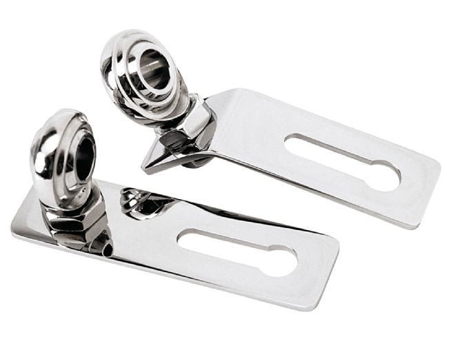 Flaming River offers frame-mount support bearing kits with straight or angled brackets with slotted holes for adjustability.
Clocking The Canceling Cam
The canceling cam has two functions; first it acts as a contact for the horn and second, it cancels, or turns off, the turn signal as the steering wheel comes back to the straight-ahead position. When the canceling cam is not clocked or timed correctly in the column the turn signals will not cancel (turn off) or they will cancel too quickly. To properly clock the canceling correctly you must first look at the top of the column as a clock face. On the canceling cam itself there is a stem that sticks up approximately 11/2 inches. Imagine this stem as the hour hand and place it at approximately the 11:30 position. This will ensure that the turn signals will cancel every time.
U-Joint Installation
The most common error made when installing a U-joint is not dimpling the shaft.
The end of the set screw is a cup point and does not sit flush on a flat surface. If the shaft is not dimpled, the set screw will feel tight but after a short time the U-joint will feel loose and you will have play in your steering system. By dimpling the shaft you increase the clamping force of the set screw creating a tight fit between the U-joint and the shaft.
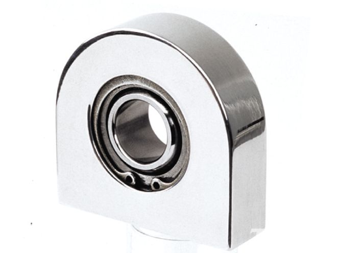 Also available is this polished-aluminum support bearing that mounts with two 1/4-inch -20 fasteners. It accepts 3/4-inch diameter shafts.
Another error that is common when installing a U-joint is creating too tight of an angle.
When the U-joint is installed at too tight of an angle, (typically more than 30 degrees, depending on the style of U-joint), it will cause a binding, or a tight spot, in the steering system. This binding is caused when the U-joint yokes are actually coming into contact with each other. In these instances a third U-joint and a support bearing have to be installed to reduce the angle. Always make sure that a red thread locker is used on the set screws to ensure that they do not loosen up from vibration.
One of the most common errors made when installing the U-joints is putting too much of the shaft into the yoke. On any universal joint you want 7/8 inch of the shaft in the yoke; this will place the shaft flush with the yoke itself. Too much shafting through the yoke causes interference with the bearing cross, which will make the U-joint feel like it is binding.