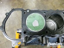
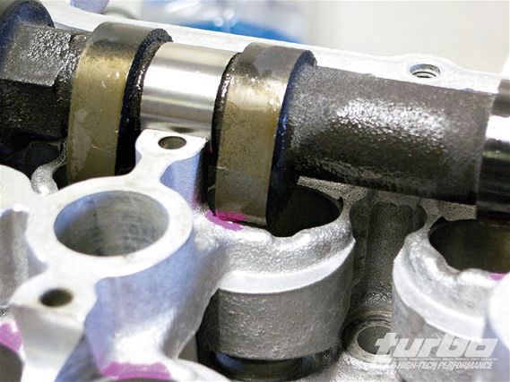
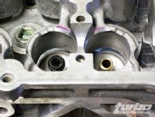
 | You can see the area in pink where the nose of the cam lobe hits the head. This is consistent throughout each bucket.
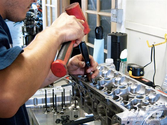
Cam installation stories have been done over and over again in high-performance automobile publications. Many times, however, proper valve timing is never really stressed. Quality cam manufacturers always include a cam card with their cams. More often than not, this goes into the trash with the shipping package. It's been a pretty long road, but our Project 750hp KA24DET has finally gotten to the point to receive the head. We haven't touched the head since it got back from Port Flow. In this installment, again with Naoto of NPD, we'll go through the assembly of the head, installation of the cams, and degreeing of the cam timing to finally finish up our long-block assembly.
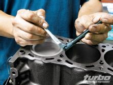
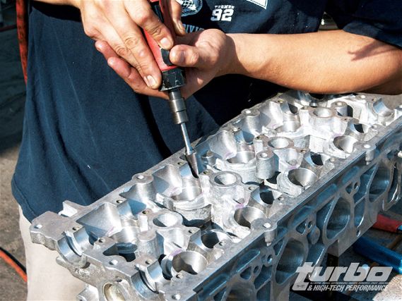 | Naoto goes slowly as he takes out material. It's really easy to cut. It's incredibly hard to put the material back on.
If there's one thing that we have learned so far in building this motor, it's the knowledge of realizing test fitment is critical when using newly developed parts. The camshafts that Naoto chose to run are a BC 272 degree with 10.19mm of lift. This is a huge difference compared to the stock bumpsticks at 256 degree and 8.73mm of lift. The increased lift enlarges the physical size of the lobe. While installing the cam into the head, we found that the bucket reliefs interfere with the rotation of the cam at the top of the lobe.
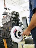
Using a die grinder, we remove just enough material out of the head to clear all the cam lobes. BC also designed the cam to work in a front-wheel-drive application. Since our engine does not utilize the factory distributor, we had to have the notch machined out. Once all the material is removed, we do another quick check to find that there is no longer any interference.
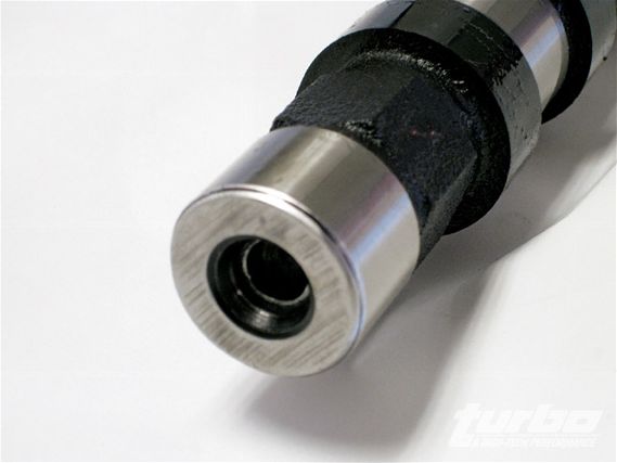 | We had a cam shop put properly cut out the notch on a cam lathe.
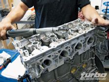
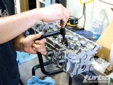
Naoto then moves onto installing the valves. As we went over in the previous issue (Aug. '08), we opted for Supertech 37.1mm nitride intake valves and 32mm inconel exhaust valves to help our head really breathe. Running a bigger cam requires that at high rpm, the valves are susceptible to floating or bouncing. To counter act this, we opted for a set of Supertech dual valvesprings. The raised seat pressure should prevent the valves from losing contact at our target of 7,200 rpm. Since the valves have already been lapped, we were set for installation.
With the valve in place, Naoto installs the lower spring seat, the valve stem seal, and spring. Depending on the motor, there might be an order to follow between the lower seat and the valve stem seal. (Honda B-series for example.) On the KA24 it can go either way. The seal should be tapped into place. Take care to not apply too much force because it may damage the seal. The spring assembly is then compressed with a valvespring compressor and the retainers and keepers are inserted. Slowly backing off the compressor, the keepers should hold the assembly in place. The same process is repeated for each valve.
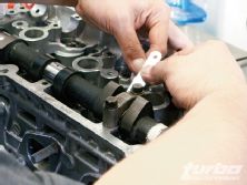
 | Make sure not to damage the valve stem seals on the way in. Putting too much stress can damage the top of the seal.
Naoto then installs the buckets and shims. We had WPC treat each one of our buckets and plan to have them do our cams and cam journals after we finish with our preliminary testing. Supertech sent us its inner shim buckets. This is an improvement in weight over the factory shim over bucket design. With our initial delivery, Supertech sent us a couple of different sized shims for us to try out. By installing our cam and using a feeler gauge, we figure how much valve lash we have and calculate the proper shim to order.
Naoto wanted to use a target valve lash of 0.20mm ( 0.02) intake and 0.25mm (0.02) exhaust. With the target shim thicknesses in hand, we had Supertech send over the shims as close as we could get them. To get tolerances even tighter, Naoto uses an oil stone and hand grinds down the shim. The oil stone only cuts a couple micron at a time so a greater amount of control can be exercised. This comes at the cost of how much time has to be spent grinding. The whole assembly is then installed and each valve is again measured for the correct lash. This also gives us a chance to make sure there are no issues with the rotation of the cam. The cams are then removed to prepare for the installation of the head.
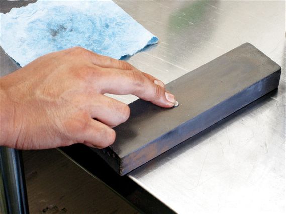 | Each shim is grinded down on an oil stone until it is the correct thickness.
We opted to use an aftermarket harmonic balancer from an SR20DET. Since the timing marks for the SR20DET and KA24DE are different, we had to make new mark on the pulley. Using a plumb bob and a chisel, Naoto puts a new mark on the pulley to match where TDC is on the stock KA24DE crank pulley.
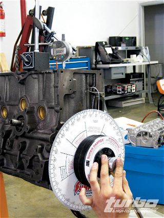
Pulling out our short block, Naoto installs his crank pulley, a degree wheel, and a dial indicator to determine TDC. This will be the starting point we'll use when degreeing our cams while spinning the motor and watching the dial indicator, he can read at that point the piston reaches true TDC and from what point the piston dwells. He now moves his indicator, in respect to the dial indicator, to the 0-degree mark on the degree wheel.
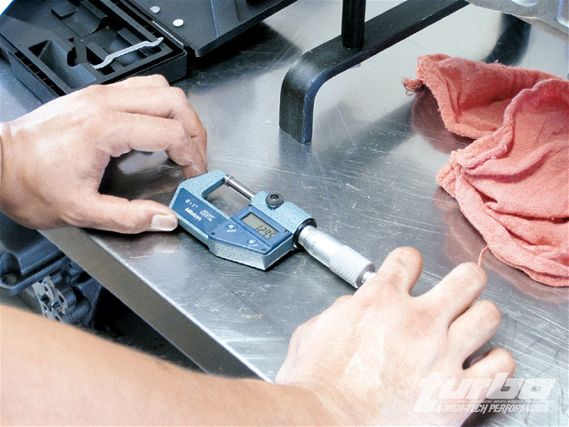 | A dial caliper is used to measure thickness along the way.
To get a better gauge of where the valves are in relation to TDC, NPD uses clay on the top of the piston. If there is even the slightest amount of interference from the valves, the clay will show it. Making sure the dowel pins are in place, the head is then mated to the block. Since we are only setting cam timing, the sealing of the head is not a concern. Therefore, we use the head gasket that we used during the machining process.
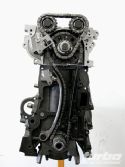
The cams are then installed with the timing chain. The KA24DE uses a two-chain system, one for the crank and one for the cams, respectively. This is separated by an intermediate idler sprocket. The upside to this is that you can service the cams without loosening the entire bottom half; only the upper chain assembly needs to be removed.
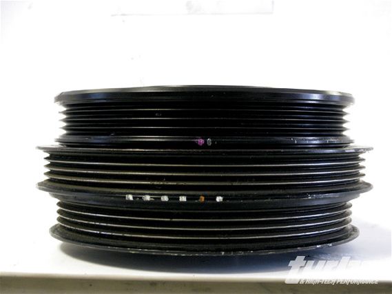 | Here you can see the timing marks on the aftermarket harmonic balancer(bottom) in relation to the stock crank pulley(top).
Our Jim Wolf Technology Cam Sprockets can finally be installed. Since the overall size of the sprockets are so small to begin with, Jim Wolf utilizes different positions on the sprocket to correspond to either advance or retard (up to 10 degrees in either direction).
The dial indicator is installed to the top of the head at cylinder one. The end of the indicator is installed to touch the bucket at an angle equal to that of the valve. The misconception is that 0 degrees in the sprocket is where it should be set to but the truth is that 0 degrees is irrelevant when using aftermarket cams. It is used only as a starting point, but never should be set without properly degreeing the cam. After determining the centerline of the cam, Naoto makes the proper adjustments to set the cam timing at 116-degree intake and 116-degee exhaust. His experience with other fixed valve timing turbo engines has shown aggressive (top end power biased) cam timing in the area of 108-112 degrees and milder (lower to midrange) settings at 118-122 degrees. Since 116 degrees is stock for S14 KA24DE and close to the middle, he decided to leave it there and do the final cam timing on the dyno.
 | Usually with the head on you would have to use a piston stopper. In this case, since the head is off, we can directly install our dial indicator to the top of the piston.
Just for the sake of knowing, he also set the cam sprockets on full-intake advance and full-exhaust retard and vice versa to see at what point there would be either piston tap or valve interference. Pulling the head off, we see no signs of contact in the clay. It turns out that with our dished designed piston there was no contact between piston and valve. Furthermore, there was no interference between intake and exhaust valves, reassuring that we can get aggressive with our timing with no fear of bending valves.
When removing the clay and timing wheel, everything is reassembled with a new head gasket. The entire assembly is set to proper torque. And there you have it. We finally have a long-block. It's safe to say that we are finally past the halfway point. To our relief, the bulk of the precision work is behind us. From here we will install the accessories and electronics, then off to the dyno we go. Please keep in mind the theories that we present are applicable to any high-performance engine, whether you are building a SR20DET or a 4G63. We are confident it will take our Project KA24DE from its meager beginning to our target 750 bhp.