Cuttin’ Corners
There’s no cheating when it comes to handling.
Understanding the principles of a vehicle’s suspension will give you a better idea as to what the vehicle, as well as the tires, are going through. When cornering, various forces affect a turn and change the direction of the vehicle, while also putting the tires under tremendous force.
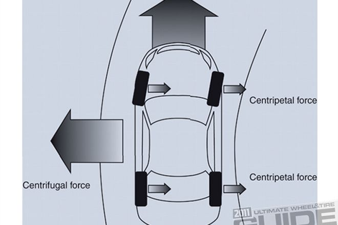
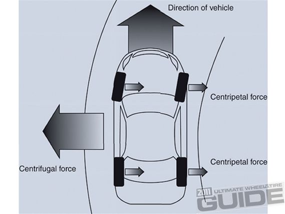
CENTRIFUGAL FORCE AND CENTRIPETAL FORCE
Centrifugal force pulls a vehicle toward the outside of the corner during a turn. This same action requires that an opposing and equal force counters the effect to ensure that stable cornering is achieved. In short, centrifugal force pushes a car in the direction of momentum and the tires grip the road to stabilize your ride; this is the gripping power that we call “cornering force.”
 |
Wheel and Tire Tech 101 - Cuttin’ Corners
|
Wheel and Tire Tech 101 - Cuttin’ Corners
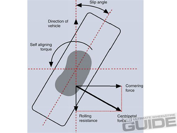
CORNERING FORCE (CF)
This is the lateral frictional force generated by a cornering tire, acting in opposition to the centrifugal force. Tire force is generated by tire slip, and in the case of cornering, tire force is proportional to slip angle.
SLIP ANGLE (SA)
Slip angle describes the deformation of the tire contact patch; this deflection of the patch deforms the tire in a fashion akin to a spring. The slip angle is measured in how much the tire’s contact patch has been twisted or sheered in relation to the wheel during cornering. This cornering force increased in proportion to the occurrence and increases in the slip angle. During normal driving, the slip angle is approximately 2 to 5 degrees with a maximum of 10 degrees.
SELF-ALIGNING TORQUE (SAT)
Self-Aligning Torque is the torque that occurs at the contact patch of the tires due to the friction entailed in cornering. This produces a major impact on the tire contact patch.
CORNERING POWER (CP)
CP is the rate at which cornering force (kgf) increases as the slip angle increases. This in turn determines the driver handling, and the higher the CP, the more cornering ability and stability the vehicle will have.
TIRE AND CORNERING FORCE/POWER
• Wet surfaces decrease the friction thus reducing overall cornering force.
• As load increases, cornering force increases, but the force will gradually decline if the load exceeds the recommended value for the tire.
• Tire stiffness will increase cornering power. Please remember that it’s dangerous when the inflation pressure or the rim width exceeds the maximum approved level.
 |
Wheel and Tire Tech 101 - Cuttin’ Corners
|
Wheel and Tire Tech 101 - Cuttin’ Corners
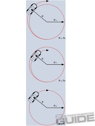
Oversteer, in an automobile, occurs when the rear tires have a loss of traction during a cornering situation. This in turn causes the rear of the vehicle to head toward the outside corner. A more technically correct definition is that oversteer is the condition when the slip angle of the rear tires exceeds that of the front tires. Rear-wheel-drive cars are generally more prone to oversteer, in particular when applying power in a tight corner.
Understeer is a term for a car handling condition during cornering in which the circular path of the vehicle’s motion is of a greater diameter than the circle indicated by the direction its wheels are pointed. In general, understeering of a vehicle will cause slightly better stability and control than oversteer.
 |
Wheel and Tire Tech 101 - Cuttin’ Corners
|
Wheel and Tire Tech 101 - Cuttin’ Corners
Neutral steer is a cornering condition in which the front and rear slip angles are roughly the same. Although seemingly an ideal state of balance, perfect neutral steer is not as stable as slight understeer.
Centering & Offset
Get a better understanding of the wheels on your car.
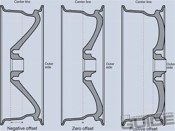
OFFSET
Offset is the location of the flat mounting surface of a wheel relative to the wheel’s centerline. Negative offset means that the mounting surface is toward the center of the car, positive offset means that it’s toward the outside of the car, or the wheel is “pulled in” toward the center. Offset affects many things other than just whether the wheel has the appearance of “sticking out” past the fender. The wrong offset can cause rubbing problems when the suspension is compressed or the wheel is turned. Offset affects the steering geometry’s scrub radius, possibly leading to problems with torque steer or self-centering characteristics.
Offset also affects the suspension’s motion ratio, which directly determines the effective spring and damper rates. Potentially, in a very heavily loaded vehicle, or with extreme changes in offsets, wheel bearing life can be affected, but this is more often talked about by truck people than by small car enthusiasts. It’s very, very important that the proper offset wheels be used.
While not directly a matter of offset, brake caliper clearance is a related issue. If you have, or plan to have big brakes on your car, be sure that your wheels, or the wheels that you’re going to use, will fit over the calipers. Spacers are available to solve the problem if they don’t, but it’s best to get a wheel with enough dish to meet your offset specs and still fit your brakes. Consulting the wheel and brake manufacturers ahead of time is wise. Many aftermarket brake companies even have templates of their brakes available that you can easily check against any wheel.
 |
Wheel and Tire Tech 101 - Cuttin’ Corners
|
Wheel and Tire Tech 101 - Cuttin’ Corners
Centering & Offset
Get a better understanding of the wheels on your car...continued
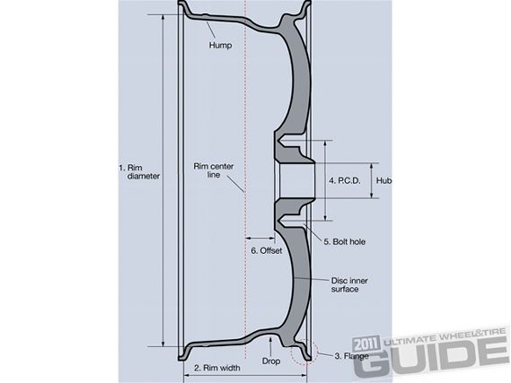
RIM MARKINGS
Look inside almost any wheel and you should find various markings that give you pertinent information on the wheel. Typically, they’re marked on the rim and, just for conversation sake, we’ll take into consideration a wheel that is marked “19x7J ET38.” The first number is quite obvious and represents that the wheel is 19 inches in diameter, while “7” is the width of the wheel and measured from the distance between the flanges that support the bead. The “J” refers to the shape of that flange; easier to understand if you imagine a steel wheel on which the lip is rolled over like a J. “ET” may or may not be present, and if you do see it is the abbreviation of einpress tief, German that translates literally as “pushed in depth,” or offset. The “38” is the offset measurement.
 |
Wheel and Tire Tech 101 - Cuttin’ Corners
|
Wheel and Tire Tech 101 - Cuttin’ Corners
CENTERING
The other element that affects directly whether a wheel can be bolted onto a car is hubcentricity. Long ago, in the deep mists of time, wheels were located by the taper of the lug nuts or bolts. This could lead to all sorts of problems, but they can be summarized by saying centering was liable to be less than perfect, and the sheer stress on wheel bolts or studs could be enormous. We’re not aware of any passenger car wheels now made that are not hubcentric.
Hubcentric wheels have a hole at their center that fits closely over a round feature on the hub, serving to center the wheel on the axis of the spindle, as well as bear the vertical weight of the vehicle. The wheel bolts or studs then serve simply to hold the wheel onto the hub, and are loaded only in tension, where they are strong. If the studs were required to absorb vertical forces, they would be loaded in single shear, the weakest arrangement for any fastener. Factory wheels are all machined to fit their specific application exactly, and some of the better aftermarket wheels are, too.
However, many aftermarket wheels rely on centering rings. This means that, instead of machining wheels specifically for each OE centering hole diameter, the wheel manufacturer machines all wheels to one size, and then uses inserts to give a centering surface of the diameter required for each application. This is obviously easier to do, and makes inventorying a complete wheel line much simpler and less costly.
If you buy wheels that use centering rings, be sure that the rings fit snugly in the wheels. If they’re loose enough to fall out, how accurately can they be locating your wheel? Some tire shops automatically remove centering rings to balance a wheel, just to make sure that there is no slop to make their balancing inaccurate.
The fact that a wheel physically bolts onto a car doesn’t necessarily mean that it “fits.” The centering surface could be too large, in which case there’s essentially no centering. Just as importantly, the offset could be wrong.
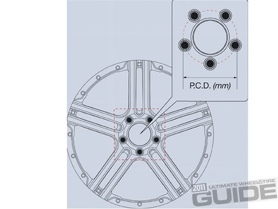
PCD
Determining your bolt pattern.
The PCD (pitch circle diameter), often referred to as the “bolt pattern,” refers to the pitch circle diameter of the bolt holes. The value varies depending on the vehicle type.
For example:
 |
Wheel and Tire Tech 101 - Cuttin’ Corners
|
Wheel and Tire Tech 101 - Cuttin’ Corners
PASSENGER CAR: 114.3 MM, 100 MM, AND 139.7 MM
TRUCK AND BUS: 222.25 MM, 285 MM, 285.75 MM, AND 335 MM
The number of bolt holes is usually four, five, or six for passenger car tires. Some aluminum wheels available on the market are multi-hole wheels, such as the nine-hole type that has four plus five bolt holes. It’s best to refer to the owner’s manual, service center, or aftermarket rim specialists to find out your PCD, but if you’re more of a hands-on person then you can always use aftermarket tools and measurements to do so. The bolt pattern or bolt circle is the diameter of an imaginary circle formed by the centers of the wheel lugs. Bolt patterns can be four-, five-, six- or eight-lug holes. A bolt circle of 4x100 would indicate a four-lug pattern on a circle with a diameter of 100 mm.
Staying Straight
Everything you need to know about caster, king pin, camber and toe.
Having the appropriate adjustments will maximize the life of your tires.
 |
Wheel and Tire Tech 101 - Cuttin’ Corners
|
Wheel and Tire Tech 101 - Cuttin’ Corners
In a nutshell, wheel alignment consists of adjusting the angles of the wheels so that they’re perpendicular to the ground and parallel to each other. The purpose of having the appropriate adjustments is to maximize tire life. In short, you want a vehicle that tracks straight and true when you’re driving along a straight and level road.
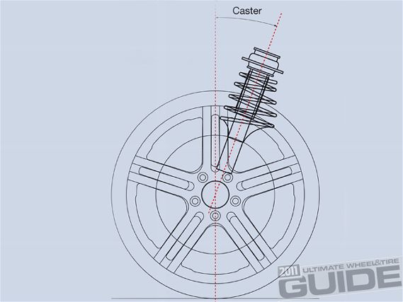
•CASTER
Caster is the degree (as represented in an angle) to which a wheel is situated ahead of or behind the top mount. It ensures the force, which attempts to restore the wheel direction to the straightforward direction when the steering wheel is turned.
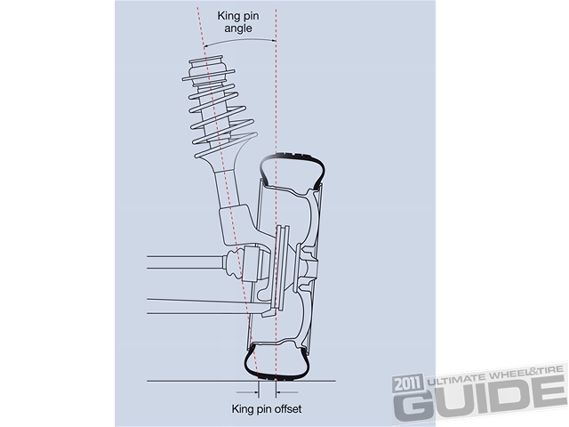
•KING PIN OFFSET (inclination)
The king pin offset is the distance from the point where the suspension axis intersects the ground to the longitudinal line that runs through the center of the tire’s contact patch. The king pin offset affects the vehicle’s steering, braking, and handling characteristics. The example, steering handling becomes lighter as the king pin angle narrows. Also, king ping angle has a major impact on the ability of the steering wheel to return to its start position.
 |
Wheel and Tire Tech 101 - Cuttin’ Corners
|
Wheel and Tire Tech 101 - Cuttin’ Corners
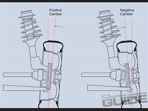
•CAMBER
Camber is the inward (negative) tilt of wheels when viewing the vehicle from the front. If the top of the wheel is leaning out from the center of the vehicle, then the camber is positive, if it’s leaning in, then the camber is negative. Excessive positive or negative camber causes wear on the outside or inside tread of the wheel one-side wear. Use of the king point offset improves steering ease.
 |
Wheel and Tire Tech 101 - Cuttin’ Corners
|
Wheel and Tire Tech 101 - Cuttin’ Corners
POSITIVE CAMBER
Outward tilt when viewed from the front
NEGATIVE CAMBER
Inward tilt when viewed from the front
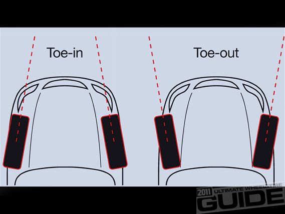
•TOE
The toe measurement is the difference in the distance between the front of the tires and the back of the tires. Since tires with camber have a tendency to slant inward or outward (camber thrust) when viewed from above, tires are set as close as possible to zero. Toe-in means that the front of the tires are closer to each other than the rear. Toe-out is just the opposite, tires with excessive toe-in or toe-out suffer more readily from feathering. The toe position will vary depending on the drive system and the type of suspension as well as between the front and rear wheels. Tires suffer from feather edge wear when improperly aligned.
 |
Wheel and Tire Tech 101 - Cuttin’ Corners
|
Wheel and Tire Tech 101 - Cuttin’ Corners
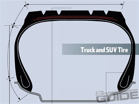
Tire Construction
Understanding the essential components of a tire.
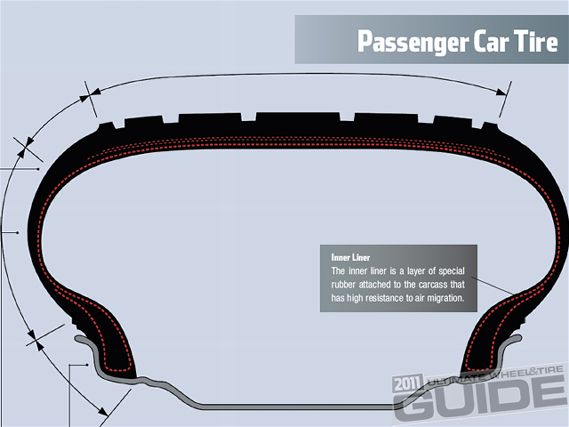
To better understand the essential components of a tire we’ve put together this diagram to give you a brief study of the structure, location, and purpose of each specific component on a tire.
 |
Wheel and Tire Tech 101 - Cuttin’ Corners
|
Wheel and Tire Tech 101 - Cuttin’ Corners
Shoulder
The shoulder on each side of the tread is designed to protect the belt and carcass of the tire and to dissipate heat generated during running to the atmosphere. There are two basic kinds of shoulder shapes: rounded and squ
Sidewall
The sidewall on each side of the tire is the section that deflects most during use. The rubber coating serves to protect the carcass and is the area where all of the notations of tire size, brand name, manufacturer, etc. are located.
Bead
The bead area supports the extremities of the carcass on each side of the tire. This is the part of the tire that anchors the tire to the wheel. Some tires also provide a lip protector on the bead which aids it in preventing the scuffing of the lips on your custom wheel.
Tread
The tread is the part of a tire that makes contact with the road surface. The tread consists of a layer of rubber, which is compounded to suit the specific application and purpose of the tire. The tire and the thickness serve to protect the belt and carcass, and depending on application tread pattern, may be tailored for several purposes including improved water drainage and better traction, as well as increased braking and cornering characteristics.
 |
Wheel and Tire Tech 101 - Cuttin’ Corners
|
Wheel and Tire Tech 101 - Cuttin’ Corners
Belt
The belt’s a reinforcement layer extends around the outer circumference of the carcass under the tread. It acts like an iron hoop and is there to improve the stiffness of the tread area.
Carcass
The carcass is the load-bearing framework that forms the body of the tire. It’s composed of rubber coated fabric or steel cords laid in a radial direction. The carcass contains the inflation pressure aiding in supporting the load and absorbing impact.
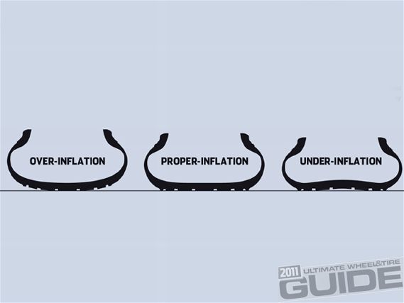
Inflation Pressures
Getting the most out of your tires.
To achieve maximum performance from your tires and the handling of your vehicle, it’s important that you have the tires properly inflated. Over-inflated tires have smaller “footprints” and produce less traction, but on the flipside, under-inflated tires have decreased durability and life.
 |
Wheel and Tire Tech 101 - Cuttin’ Corners
|
Wheel and Tire Tech 101 - Cuttin’ Corners
Although both cases have their negative side effects, it’s important to remember that a minimal variance of 6 psi will significantly impair performance. In order for the tire to have optimum ground contact and to transfer power effectively, a vehicle’s tires must be properly inflated and aligned.
Furthermore, correct inflation pressures prove optimum comfort, performance, and longevity. To add to the importance of proper inflation, one must consider that a proper psi settings also stabilizes the vehicle’s structural rigidity. From the tire’s structure, traction, and responsiveness all of the way to handling, it’s very important to understand.
OVER-INFLATION:
• Abnormal tire wear—center wear of tread
• Jumpy ride discomfort
• Vehicle stability decrease
UNDER-INFLATION:
• 6 psi under will weaken the tire’s internal structure and eventually lead to tire failure.
• Lower psi also create more tire deflection.
• Tread life can be diminished as much as 25 percent.
• Under-inflation will also cause irregularities in tire wear and provide extreme shoulder wear.
• Separation and cord break can happen due to heat buildup.
• Poor cornering
• Hydroplaning
• Standing wave phenomenon
TIPS
• Because air expands as the temperature rises, inflation pressure increases after running.
• It’s best to check inflation pressure when the tire is cold.
• Special care is required for tire inspection of front-wheel-drive vehicles because the front wheels bear a heavier load.
• If a hot tire shows less than the recommended cold inflation pressure, then the tire is under-inflated. Inflate it to the recommended cold inflation pressure plus an additional 10 percent. As soon as the tire cools downs, recheck and set the pressure to the recommended level.
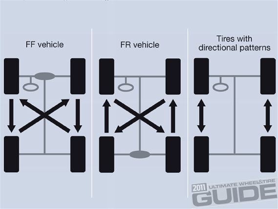
Tire Rotation
A change in position can make a big difference.
Using tires for a long period of time in the same positions will typically create more wear, especially on the front. The front tires wear quicker than the rear because they generate more use since they steer, brake and take the most of the load during cornering. For longer tire life, it’s necessary to perform tire position rotations periodically as recommended by the tire manufacturer, but tire rotations are usually recommended every 5,000 to 7,000 miles. Please note that tire rotation is not possible with certain applications such as staggered fitments.
 |
Wheel and Tire Tech 101 - Cuttin’ Corners
|
Wheel and Tire Tech 101 - Cuttin’ Corners
Advantages
• Prevention of uneven
tread wear.
• Extension of tire service life.
• Averaging of tire fatigue.
Tire Replacement
Triangular-shaped marks on the sidewall show the tread groove position of the tread wear indicators (TWI). The TWI represent 1.6 mm of remaining tread depth, at which time the tire should be replaced.
Arrow-shaped marks on the sidewall show the tread groove position of the “platform wear indicators.” This shows 50-percent of the wear of original tread depth, at which time it should no longer be used as a winter tire, but can be used as a normal tire.
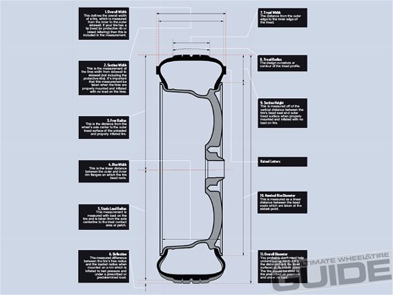
Wheel & Tire Dynamics
Understanding the relationship between rims and rubber.
To better appreciate the dynamic relationship between a wheel and a tire you have to first understand the mechanical characteristics of their unison. Let’s face it, there’s no other single component more important than your rims and tires since this is what everything else rests on. So to get a better education on this versatile subject we spoke with Mark Chung of Yokohama Tires. At the heart of the conversation was a detailed breakdown of wheel and tire dynamics. We’ve also created a detailed outline of the measurements that you should better understand as both a consumer and enthusiast of aftermarket wheels.
 |
Wheel and Tire Tech 101 - Cuttin’ Corners
|
Wheel and Tire Tech 101 - Cuttin’ Corners
1.Overall Width
This defines the overall width of a tire, which is measured from the inner to the outer sidewall. If your tire has a lip bead (or protective rib or raised lettering) then this is included in the measurement.
2.Section Width
This is the measurement of the tires width from sidewall to sidewall (not including the protective ribs). It’s important that this measurement be taken when the tires are properly mounted and inflated with no load on the tires.
3.Free Radius
This is the distance from the wheel’s axle center to the outer tread surface of the unloaded and properly inflated tire.
4. Rim Width
This is the linear distance between the outer and inner rim flanges on which the tire bead rests.
5. Static Load Radius
This measurement is measured with load on the tire and is taken from the axle centerline to the treat contact area or patch.
6. Deflection
The measured difference between the tire’s free radius and the loaded radius when mounted on a rim which is inflated to test pressure and under a prescribed or predetermined load.
7. Tread Width
The distance from the outer edge to the inner edge of the tread.
8. Tread Radius
The design curvature or contour of the tread profile.
Raised Letters
10. Nominal Rim Diameter
This is measured as a linear distance between the bead seats which are taken at the widest point.
11. Overall Diameter
You probably don’t need help understanding this but it’s the distance from the tread surfaces at its widest point. The tire should be aired to the prescribed air pressure and under no load.
Tire Diameter
Determining how big your tire will be.
CALCULATING OVERALL TIRE DIAMETER
To calculate the overall tire diameter you only need the size of the tire. The following formula will help you determine the tire diameter and give you a good idea as to whether or not that new rim and tire combo you want will fit. Just compare the overall diameter (of the desired tire) in inches to your stock tire and this will allow you to measure up your vehicle to see if it will fit with or without modifications. You must also take into consideration the width of the tire you are proposing to put on, just because the OD matches doesn’t mean the width won’t put a damper on your newfound fitment. Please note that all oversized fitments should be left to a professional they can tell you what – if any – modifications need to be performed.
 |
Wheel and Tire Tech 101 - Cuttin’ Corners
|
Wheel and Tire Tech 101 - Cuttin’ Corners
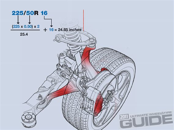
For example, if the tire size is 225/50R 16 the equation will be implemented as follows:
When upsizing rims on a vehicle it is also important to
consider the following:
Be sure that there is no contact with the tire and the inner fender liner
FIX: You can always heat up the fender liner and remold it or in some instances you may have to remove the fender liner. Please note that removing the fender liner may cause excessive road noise from debris bouncing off bare metal and that valuable electronics may now be exposed. Inspect carefully!
Be sure there is not contact on any control arms, spring perch, or any other obstructions that may be there.
FIX: Many shops will trim metal brackets to avoid any minor scraping. This should be left to an expert and be advised that damage to the body or paint may occur if not done properly.
Be sure that the case nut under the spring perch does not touch the top or inner sidewall of the tire. As the tires heat up they will expand so keep that in mind.
FIX: Run a slightly smaller tire. In some cases the nut is shaved down slightly to add extra clearance. Please note that we do not recommend this but are just educating you on what is sometimes done. If you choose to do this make sure that it is left to a professional as shaving too much of this bolt may have detrimental consequences.
Be sure that the inner lips on your fender don’t contact any part of the tire while driving straight, during compression or hard cornering.
FIX: You can have the fenders either rolled or cut. If you do roll fenders be sure to have an expert do it to prevent paint chipping of unevenly (and ragged) fenders. When cutting fenders be sure to sand down the cut edges to ensure that they are smooth. When done you should apply a coat of rust-proofing or paint to seal the open area.