Let's Get Regulated
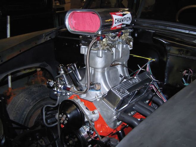
Philip Peacock; Buffalo, NY I am a longtime reader, and I enjoy the average-car-guy-build way of doing things. I've got a fuel line or fuel pump problem for you. The car is a 2,400-pound Henry J with a 383ci small-block Chevy, Edelbrock RPM heads, a TR1X tunnel-ram with two 450-cfm Holley carbs, a Herbert mechanical flat-tappet cam with 238 degrees of duration and 0.538-inch lift, and 10.47:1 compression. The fuel system consists of a Mallory 110 pump, a Mallory 140 filter, and a 1/2-inch aluminum line up to the 12-803 Holley regulator. I've come out of the regulator with a single, -6 line to dual, inline banjo fittings connected to the carbs, with pressure set at 7.5 pounds with a gauge on regulator.
The engine sounds like it's starving for fuel at around 5,700 rpm, so it was suggested to run dual 12-803 regulators with a line out of each to each carb with a straight fitting instead of the banjo. What is the difference between just disconnecting the pressure gauge and running the second fuel line out of the one regulator? I have attached a photo of the current setup to get the visual.
Jeff Smith:This sounds like a fun ride - fuel pump problems always are. You get extra style points for that body. From your description, I'm not sure your plumbing job on the fuel line is really at fault. The Holley 12-803 pressure regulator has been around for decades. It uses a spring-loaded check ball to establish the required fuel pressure, and the ball is 0.220 inch in diameter. When compared with a -6 fuel line (a theoretical inside diameter of 0.375 inch), you might assume the regulator is the restriction. But let's start at the carburetor and work our way toward the pump. The typical small-cfm Holley carburetor is equipped with a pair of 0.097-inch-diameter needle-and-seat assemblies. We used the term "theoretical" when describing the -6 fuel line because common AN fittings generally restrict the inside diameter to something significantly less than 0.375 inch. But for the purposes of our discussion, we'll leave it at 3?8 inch. Moving further upstream, we come to the regulator. After adding the potential flow area of four 0.097 needle-and-seat assemblies and comparing that with a single 0.220-inch check ball in the Holley regulator, I initially thought I'd found the restriction. But when I did the math, it was revealed that the four needles are only 78 percent of the area of the regulator. A second regulator with more flow area would probably help by reducing the flow restriction, but perhaps this isn't really the problem. The assumption we're making is that we have good fuel pressure at all times.
I'd suggest plumbing at least a temporary fuel-pressure gauge to the cowl so you can watch the fuel pressure during a test pass. That Mallory pump is rated at 120 gallons per hour at 6 psi, which converts to well in excess of 1,000 hp worth of fuel flow. So in theory, your pump has the capacity, but we've seen many cases in which restrictions on the pressure side, restrictions on the inlet side of the pump, inadequate fuel tank vents, and even voltage drops on the electrical side all affect pump capacity and create fuel pump problems. Rather than testing all these separate systems, I'd suggest making a pass with the car and watching the fuel pressure. If the pressure begins to drop halfway down the track, you'll know you have a less than optimal system and can begin to check the above systems as possible corks. Another suggestion is that you may have to raise the static fuel pressure setting at idle to maintain that 6 psi under full load. If the fuel pressure drops as the car runs down the course, it's an indication of a restriction or a reduction in pump output. Your system is what is termed a dead-head system. At idle, there is very little fuel used when you set the pressure. But under WOT, fuel demand is high, and the pressure might drop. As an alternative to this setup, we installed a return system in my orange Chevelle that uses a return regulator to set system pressure at 10 psi, then attached the outlet to a dead-head regulator (like your 12-803) to set the pressure to the carb. This way, the fuel pump does not have to work as hard, as the fuel is returned back to the tank. And under load, we're using 10 psi (or more if desired) to push fuel forward to the dead-head regulator to feed the carbs.
Of course, it's also possible that the problem is not fuel-delivery related. We know of an enthusiast who upgraded his fuel-delivery system only to discover that his real problem was that the throttle was opening only 60 percent. The cure was a 30-second adjustment to the throttle linkage after he spent days building a killer fuel system. Other classic issues that could cause the engine to lie down at higher engine speeds include retarded ignition timing, or, my personal favorite, weak valvesprings. More than likely, your issue will be easily identified after first determining whether the fuel pressure drops during the run. Sometimes the simplest solutions are the best.
The Mighty 10-Bolt
Kory Errico; North Haledon, NJ: I have been reading your magazine since the '70s and enjoy it greatly. I've tried other subscriptions but always return to you as my main mag. This is my first time contacting Car Craft for help. I have a small-block Olds in my '72 4-4-2 making more than 450 hp and want to add a bottle. The car has the 8.5 GM 10-bolt. Is there anything I can do to get this rear to handle 600-plus horsepower? I was hoping to keep the sleeper look going by not swapping out the rear. I would love to hear your suggestions for either type of setup. I have PMT-Fab upper and lower trailing arms and factory frame braces with Lakewood traction bars, and I've been using the narrow 225/70R14 BFGoodrich radials to keep the rear in one piece. Thank you.
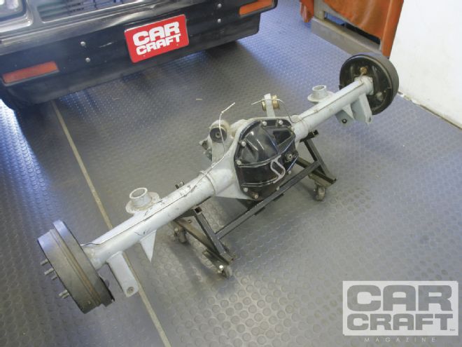
Jeff Smith: The common assumption about GM 10-bolt rearends is that they are all weak and all the same, but that's not true. The early, original 10-bolt was a lighter-duty version of the 12-bolt, using an 8.2-inch-diameter ring gear, a small-diameter shaft pinion gear, and spindly, 28-spline axles. Around 1971, GM essentially integrated much of the strength of the 12-bolt into a corporate 10-bolt. This new rear uses an 8.5-inch ring gear that is only 0.375 inch (diameter) smaller than the 12-bolt and uses 10 larger 7?16-inch retaining bolts. The pinion gear is also the same shaft diameter as on the 12-bolt at 1.625 inches, so it is just as strong. So you can certainly strengthen the 8.5-inch rear to be pretty durable, and there are plenty of parts to choose from.
We looked in the Strange catalog and found all kinds of pieces, including an excellent steel pinion yoke that will accept the stronger and larger 1350-style U-joint (PN U-1605; $89.95 Summit Racing), a Strange Pro Series limited slip (PN R5083, $518.95 Summit), a pair of aluminum, high-strength differential caps (PN H-1120, $89.95 Summit), an LPW aluminum rear cover with retaining bolts (PN R5203, $149.95 Summit), a Strange 1550 steel axle package with bearings (PN P3104, $396.95), and a pair of large Ford bearing housing ends that are required with the axles (PN H1143, $69.95 Summit). I'm assuming you'll use your existing gears with this upgrade. We included the limited-slip because it will accommodate the 30-spline axles that are a necessity to improve durability. If we include $300 for labor to weld the housing ends, weld the tubes into the housing, and install the internal parts, the total comes to a little more than $1,600. If you want to add a set of gears to this upgrade, you're looking at an additional $180, which pushes the total to almost $1,800.
 If you are looking for a rear-axle assembly with ultimate durability, it's tough to beat the Strange S-60 bolt-in. Strange offers this housing in several configurations to fit many popular chassis combinations.
Just to give you something else to ponder, we checked out the Strange S-60 conversion for your car. Strange has created a new Dana 60 housing that includes the upper and lower control-arm mounting fixtures to bolt directly into any '64 to '72 GM A-body. The S-60 offers the advantage of a much larger Dana 60 9.5-inch ring gear, the same large 3.150-inch housing ends, monster 35-spline axles that are 50 percent stronger in terms of torque capacity than the 30-spline GM pieces, and fully welded tubes where they enter the centersection. The knock in the past with the Dana has been that it is heavy. Certainly the larger-diameter ring gear will add some heft, but we're talking only 20 pounds over a comparable 12-bolt. We checked the price at Summit Racing (PN PRSAO5; $1,994.95), which could be only about $100 to $300 more than what you would have to put into your existing 8.5. In terms of durability per dollar, it's tough to beat the S-60.
One consideration is whether the Dana 60–style assembly uses more power to turn. We did that test back in the June '08 issue ("The Great Rear Axle Comparo," pg. 40) when we compared the 12-bolt with the Strange S-60 and the Ford 9-inch. We saw very little rear-wheel power difference with the Dana compared with the 12-bolt, mainly because the pinion offset (the relationship of the pinion to the ring gear centerline) is essentially the same between the two rear-axle assemblies. The big power absorber was the Ford 9-inch, on which we measured between a 5hp and 7hp loss compared with the 12-bolt above 5,000 engine rpm. So that leaves weight as the only other consideration, and if the brake package is the same, the S-60 is negligibly heavier. As for the cost of all this, you could recoup perhaps $300 to $500 by selling your existing 8.5-inch 10-bolt, at which point you'd be money ahead and have a rearend you can install, and you'd never have to worry about durability.
The Standing Mile
James Moore; via CarCraft.com: I'm building a car for land speed racing with the East Coast Timing Association (ECTA). I came across a four-speed Jerico transmission for cheap. It's been gone through and is a solid transmission. It came with a set of clutches about the size of a coffee cup coaster, and while I'm sure they're great, I know they're going to wear out quickly in the stop-and-go of the pits. Since I don't really need such an exotic (or expensive!) clutch setup, can you recommend something for me? The car it's going in is a gutted '91 Mazda RX-7 with a warmed-up small-block Chevy and an IRS out of a C4 Corvette with 3.08:1 gears. Right now, I'm estimating 400 to 450 rwhp out of the small-block to sort the bugs out. I saw in a story called "Poor Man's Jerico" that you guys were running a Centerforce clutch. Would something like that work for me, too? I've got a Centerforce Dual-Friction in my Mustang right now, and I like it a lot. What would you recommend for a clutch and flywheel setup?
Jeff Smith: This sounds like a real rocket, James, with 450 hp in a car that probably only weighs around 2,800 pounds. Given the mild power, the C4 IRS, and the reduced overall weight, a Centerforce Dual Friction 11-inch, single-disc clutch would probably be a good addition. The larger disc offers more surface area, which when combined with a given clamp load from the pressure plate and the coefficient of friction of the clutch disc can create the overall torque capacity of the clutch assembly. The reason oval-track and road racers use the smaller 8-inch multiple clutch disc is to reduce weight, which has a tremendous effect on the amount of power it takes to accelerate the mass of the clutch and flywheel assembly. To simplify that, it takes less power to accelerate a given mass with a radius that is 4 inches from the crank centerline than it does to accelerate the same mass where the radius is farther out, such as at 5.5 inches. We mention all this because Centerforce offers a couple of different options when it comes to the clutches. In your case, where the car will be used primarily as a race car, you might want to look into what Centerforce calls its Light Metal clutch assembly. First, you have an option of an aluminum 11- (or 10.5-) inch flywheel. It's no surprise that the steel flywheel weighs significantly more at 36 pounds compared with the aluminum's 15.5 pounds for the 11-inch-diameter wheels. While reducing the weight by more than 50 percent is dramatic, the effect is even greater with a larger diameter. Centerforce tends to reduce the weight of its steel flywheels to reduce the inertia, but there is still a major advantage to the aluminum flywheel. We won't get into the math because it can get complex, but the advantage is significant. The downside to an aluminum flywheel is that by reducing the mass, at low speeds it is difficult to accelerate lightly from a dead stop. That's why you see the NASCAR and IndyCars spin their tires when they leave a pit stop during a race, as it is very easy to stall the engine with a lightweight flywheel and clutch assembly.
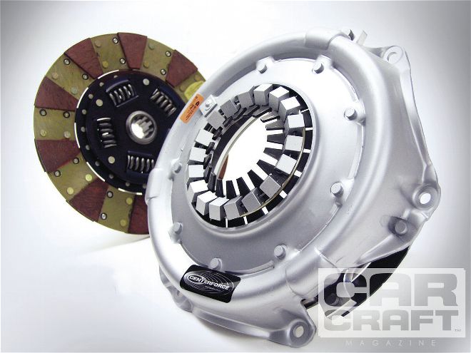 We've used this Light Metal Clutch assembly and aluminum flywheel in our '65 Chevelle on a road course, and it works brilliantly. But it’s less fun on the street because its low inertia makes leaving from a dead stop difficult. This complete rotating assembly weighs only 39 pounds.
Taking this one step further, the Light Metal Clutch system uses a steel cover over an aluminum pressure plate using a steel friction surface (similar to what is used on the aluminum flywheel). This further reduces the total weight of the clutch package and can get you down to an overall weight of around 40 pounds. This compares with something closer to 60 pounds with a conventional steel flywheel and Centerforce pressure plate. The bottom line is a lighter flywheel and clutch assembly will result in more power transferred to the rear tires to accelerate as opposed to using that power just to accelerate the clutch assembly. Of course, this acceleration advantage doesn't come without a price. Just the 11-inch aluminum flywheel (PN 900120) prices out at $629.95 from Summit Racing. The Light Metal Clutch assembly for the above flywheel is also pricey. A standard Dual Friction clutch and pressure plate package (PN DF 271675) comes in at $356.95 from Summit. Of course, you could use the Dual Friction package with the aluminum flywheel and save a little money, and the ultimate clamp load performance would be similar. You should use an SFI-spec flywheel (which all Centerforce pieces are) for this application because you don't want to witness what happens when a flywheel explodes at 6,000 rpm. We've probably created as many new questions as we've answered, but at least you have more information with which to make a decision.
A Matter of Timing
Eddie Allison; Houston, TX: I have been playing around with small-blocks for about 20 years. I also have a mechanical engineering degree, so I'd like to think I know something about camshafts. However, there is something I cannot seem to get my head around. How can you get a camshaft that has set specifications when the manufacturer says it is ground 4 degrees advanced? I understand that I can install a cam advanced or retarded, but once it is ground the specs are set. I was reviewing an old Hot Rod article, and in one table, some of the cam companies recommend certain cam specs that are ground 4 degrees advanced. So are they saying they grind 4 degrees from a certain blank? Are the specs they give the actual specs--the blank specs--or do I need to factor in some math for the 4 degrees? I like to know exactly what I am getting before I purchase and install. I have asked a few of my friends, but they don't get it either, so I hope I am not the only basket case.
Jeff Smith: When a camshaft manufacturer grinds a camshaft, the relationship between the intake and exhaust establishes the lobe-separation angle. Let's use a typical cam as an example and give it a 113-degree lobe-separation angle. It may be coincidence, but I've noticed that the intake centerline and the lobe-separation angle are always the same number if the cam is not ground advanced. So in this case, the intake centerline would also be 113 degrees. However, cam grinders often decide to grind advance into the camshaft before you install it in the engine. This means the cam grinder moves the intake centerline ahead relative to the No. 1 piston at top dead center (TDC). This is done for a couple of reasons. First, it's a fair bet that cam companies assume most guys will not make the effort to degree their camshaft, so advancing the cam compensates for a possible retarded cam position. Perhaps more important, advancing the camshaft also improves low-speed throttle response, as car crafters are famous for ordering camshafts that are a little too big. Long-duration cams sacrifice low-speed torque and throttle response, so advancing the cam is an easy way to recapture some of that lost torque and idle signal for the carburetor.
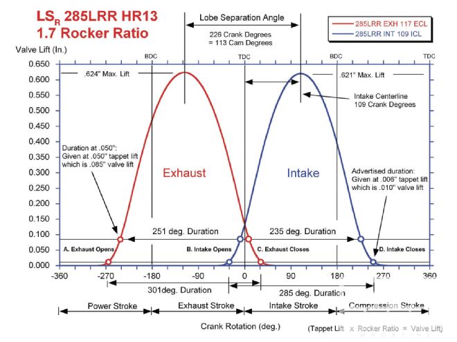 This Comp Cams illustration makes it easier to understand the relationship between intake centerline and the remainder of the cam operations.
As you've noticed, the easiest way to spot this built-in advance is by comparing the intake centerline number with the lobe-separation angle. What the cam grinder has done is merely advanced the intake centerline in relation to what would have been its original position. If you are going to use one of these camshafts and you intend to degree it, it's important to know if it's already been advanced. If it has, you would not want to advance the cam further.
Over the years, I've collected some obscure cam-timing math you might find amusing/helpful/geeky depending on your point of view. Let's condense it down to the essentials.
We'll use a Comp Cams XE 284 flat-tappet hydraulic cam for a small-block Chevy as an example. The Comp specs for this cam are 284/296 degrees of advertised duration, 240/246 degrees at 0.050, with 0.507/0.510-inch valve lift and a lobe-separation angle of 110 degrees.
To find duration at any tappet- checking height (0.004, 0.006, 0.050, or 0.100 inch tappet lift):
Calculate exhaust duration the same way.
You can also find the intake centerline with a simple equation:
There is a discrepancy between our calculations and the published cam card, as the cam card lists the intake centerline at 106 degrees. That could be attributed to this being an asymmetrical lobe in which the max lobe lift point used to determine intake centerline might not be the true lobe intake centerline. Or it could just be simple rounding off of numbers. The numbers are so close that a 1.5-degree difference isn't critical.
So by our calculations (using the 0.006-spec numbers listed on the cam card), the intake centerline is 107.5 degrees after top dead center (ATDC) while the lobe-separation angle is 110 degrees. That means that the intake lobe was ground 2.5 degrees advanced relative to the straight up lobe-separation angle of 110 degrees.