When I first started tinkering with cars, one of the first big hurdles was how to complete certain tasks without the ability to weld. Shaving trim holes, repairing rusty panels, or fabricating custom brackets all required the ability to melt and mate two different pieces of metal. And while there are a number of ways to tackle such tasks, arguably the easiest is MIG welding.
Literally a "point and shoot" method, MIG or Metal Inert Gas welding is a process that uses electricity to melt and join together two pieces of metal. The learning curve for MIG welding is relatively gradual, making it the perfect process for the beginner to pick up and learn in his own backyard. What isn't gradual, however, is the slippery slope that one finds themselves on once that basic technique is sorted out. Welding up those trim holes leads to repairing those rusty door corners. Pretty soon you'll find yourself welding up suspension components, fabricating custom motor mounts, or crafting custom headers, all using the same MIG or GMAW (Gas Metal Arc Welding) technique. But what that slope will eventually lead to is the desire to take one's welding to the next level; and that level is TIG.
TIG Welding 101
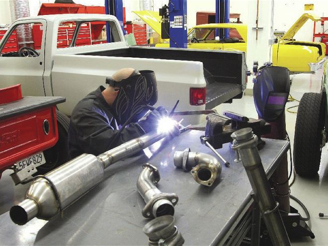
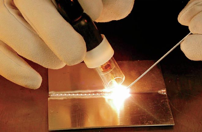
Gas Tungsten Arc Welding (GTAW) or TIG (Tungsten Inert Gas) welding is an arc welding process that uses a tungsten electrode to produce an electric arc that jumps between it and the work piece, heating up the material and hence creating the weld. An inert shielding gas (typically argon or helium) protects the weld area from atmospheric contamination. Like MIG welding, a filler metal is typically used to create most welds, but unlike the MIG process that uses a continuous wire electrode, TIG uses an external filler rod combined with the tungsten electrode to complete the weld. This "hand dance" is what makes TIG welding more difficult than the MIG process to learn and much more challenging to master. The big advantage to a TIG is control. You have control over the complete process by utilizing a remote amperage control (foot pedal or hand amp control) you have the ability to vary the amperage while you are welding, and since the filler metal is fed in by hand, you are controlling both the amperage and filler metal while you are welding. The benefit when doing custom work is the appearance — the "roll of dimes" look.
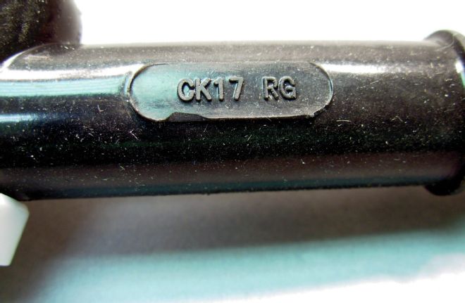
TIG torch identification is the first step in determining what components are compatible with your setup. Molded into the neck of all TIG torches are numbers that identify the torch. This torch is designated CK17 RG. The letters "CK" denotes the torch is made by CK Worldwide while the "RG" designates it as a rigid neck torch. While it's helpful to know the manufacture, it's the numbers that are important. The "17" designates it is as a 17-series 150-amp air cooled TIG torch. This arms you with all the information you'll need to purchase consumables for said torch, regardless of the make.
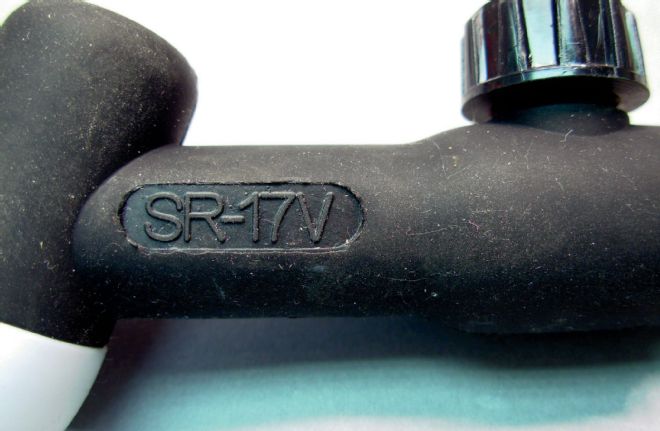
This example is also a 17-series torch, with the added "SR" designation identifying it as being manufactured from silicone rubber. The "V" designates this torch head has a valve in it, which is used to turn on and off the shield gas. Modern TIG welding machines have a gas solenoid valve in the machine and do not require such a valve in the torch. Even though this does not have the "RG" designation, this is also a rigid neck torch head.
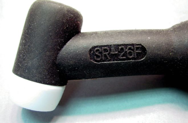
This torch is a 26-series 200-amp air-cooled torch. The "F" at the end designates this as a flexible neck torch — yes, the neck actually can be bent.
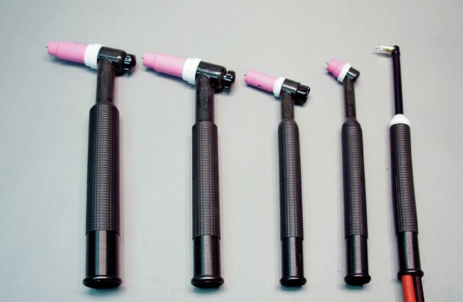
The relative size between the different torch types is easily distinguished when placed side by side. Individually, it's more difficult without using the molded ID numeration. Note that all the torches have "standard" setups with short back caps. If you were working in a tight place, either a 9/20 or a 24/24W torch would give you the best access.
Below is a list of the common TIG torches:
Model Series Amperage/Duty Cycle Cooling SR-9 9 series 125 amps @ 100% Air SR-17 17 series 150 amps @ 100% Air SR-18 18 series 350 amps @ 100% Water SR-20 20 series 250 amps @ 100% Water SR-24 24 series 80 amps @ 100% Air SR-26 26 Series 200 amps @ 100% AirBenefits
One of the most rewarding aspects of TIG welding that I found is the ability to weld different materials, such as stainless or aluminum without changing my entire welding setup. Using the MIG process, welding aluminum with any success requires a separate "spool gun" to feed the extremely soft and malleable aluminum filler wire into the weld area. These can cost a few hundred dollars in addition to the initial MIG machine purchase. For most classic truck builds, it's hard to justify the cost for the additional hardware versus the occasional use that it may see. On the flipside, changing from welding steel to aluminum using the TIG process is a simple switch of the machine from DCEN (direct current electrode negative) mode to AC (alternating current) mode and changing filler rod. In the past, this also may have required changing the tungsten type, but with today's 1½-percent Lanthanated tungsten (recognized by their blue tip) it's simple to switch between the different modes without changing the tungsten, so long as the diameter meets the need (we'll cover tungsten size in a minute…).
The ability to weld a number of different materials is extremely liberating to the fabricator or custom builder and is one of the most appreciated side effects of the TIG welding process for me. After a whole lot of practice TIG welding mild steel, I swapped out the ER70S-6 mild steel rod for some 308L stainless steel rod and was able to fabricate a stainless steel exhaust system on my C10. The result was way nicer than any MIG welded aluminized exhaust system that I'd built in the past and even looked kinda professional (imagine that!). Switching my machine from DC to AC mode and picking up some 4043 aluminum rod, I was able to weld up the induction plumbing for the supercharged LS on the same project. That would not have been possible without the ability to TIG weld and would have cost a small fortune to have fabricated by a third party. The doors that open once the TIG process is mastered is truly game changing when it comes to custom truck building.
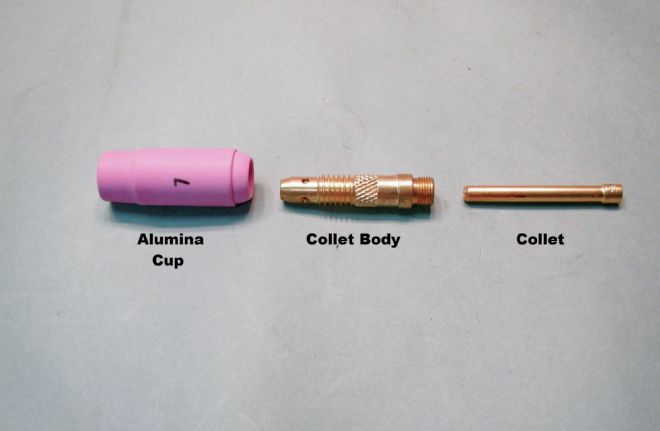
With the torches identified, let's get up to speed on the parts. These are the three consumable parts found on the front end of a TIG torch. These parts would be considered a "standard setup" and are for a 17/18/26 series torch.
The alumina cup is made from a ceramic alumina oxide material and directs the shield gas around the tungsten and the weld. You can see the number on the alumina cup — this refers to the inside diameter of the cup in 1⁄16-inch. So the #7 cup in the example above has a 7⁄16-inch inside diameter. Alumina cups tend to break when you drop your torch, so you might want to keep some spares on hand.
The collet body is sized to match the tungsten diameter. If you are using 1⁄16-inch tungsten, you would use a 1⁄16-inch collet body. The most common tungsten diameters are .040-inch, 1⁄16-inch, 3⁄32-inch, and 1⁄8-inch, so collet bodies are available in all of those diameters. The collet body also has four cross-drilled holes. The shield gas comes out through the four holes.
The collet is also size to match the tungsten diameter. The back cap, not shown, pushes the collet against the collet body, which locks the tungsten into place. The combination of the collet and collet body is what takes the electrical current the welder is generating, and transfers it into the tungsten, so it is important to keep these parts in good working condition.
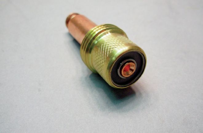
The gas lens setup is another configuration for the front of a TIG torch. With the standard setup, the gas comes out through the four holes in the collet body. When it exits the holes, it hits the inside of the alumina cup and has to make a 90-degree turn to go out the end of the alumina cup. With a gas lens, the shield gas exits the gas lens through a series of screens in the end of the gas lens. The screens help smooth the flow of gas and it exits the gas lens directed at the end of the alumina cup. Generally speaking, you would always use a gas lens because it provides better gas coverage around the weld.
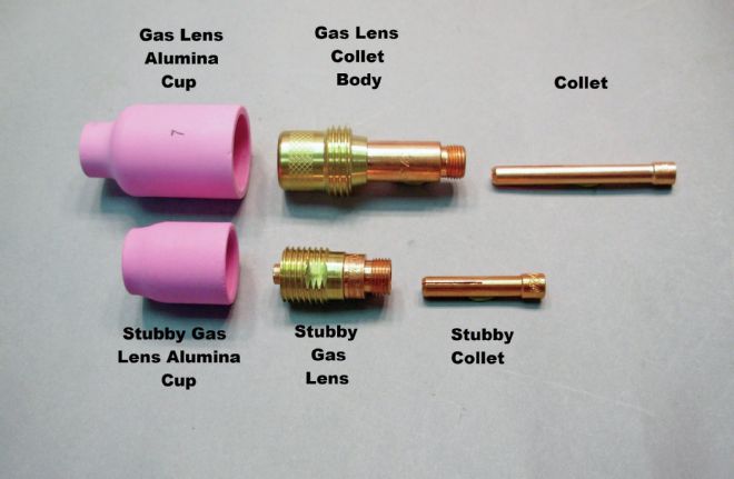
In addition to the standard gas lens setup (top), a stubby gas lens setup is also available (bottom). With the standard setup, you can see the drawback; the parts are much larger, so welding in tight areas can be difficult. The stubby gas lens gives you the best of both worlds, a gas lens in a compact size, enabling you to work in tight areas. Both examples are for a 17/18/26 series torch.
Another front end style is the Pyrex Cup (P/N PYREX17SKIT). This combines a gas lens with a clear Pyrex cup, giving the user unparalleled visibility. The drawback is that these cups are fragile and expensive. However, if you can't see what you are welding, they make all the difference in the world.
A Learning Experience
But with all that experience under my belt, there were still a few things that managed to elude me. Like most self-taught students, I didn't have anyone around to tell me what I might be doing wrong. I managed to fumble my way through things, not really knowing how or why I was having difficulty. When I welded aluminum, I turned up the amps, burning out the tungsten tip in the process. Switching over to 22-gauge mild steel sheet and I found that the arc was harder to control, wandered more than it should, and tended to burn through before the rod would melt, causing me to constantly "chase" the weld along the seam. I managed to fight my way through these issues, but it was a true epiphany-type situation when I realized the error of my ways. Incorrect tungsten and filler rod size were the culprits, but before I fumbled my way further down the worm hole, I decided to contact a professional in the form of Jeff Noland at HTP America with the hope that he could shed a little light (shielding gas included!) on my welding situation. Jeff managed to not only school me on tungsten and filler rod size selection, but also brought up a number of helpful tips and tricks relating to the TIG torch itself. Take a look and see for yourself. I hope it helps you as much as it's helped me!
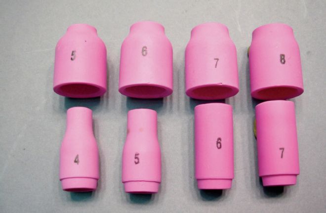
What about cup size? How do you know what cup size to run? The picture at right shows 9/20 series gas lens and 17/18/26 series stubby gas lens alumina cups on the top row (they are the same), and 9/20 series standard parts and 17/18/26 series stubby standard parts on the bottom (they are also the same).
As we indicated earlier, the number on the cup refers to the ID in 1⁄16-inch. Now let's make a few assumptions. We are going to assume you are using this welder in your garage on home projects and not welding eight hours a day in a shop. If you are welding at home, the cost of the shielding gas is really not a huge concern. It certainly is a concern, but in the overall scheme of things, it is not really a big concern. It is obviously much more expensive in a material and time standpoint if you ruin a piece due to inadequate gas coverage, because you were trying to save on gas. If we were not welding in a tight place, where torch size was not an issue, then the go-to setup would always be a gas lens with a #7 or #8 cup running a flow rate between 10 and 20 cfh. This would give us the best gas coverage, allow us to stick the tungsten out a little further if needed, and possibly compensate for air movement (wind, fan, heater, etc.) blowing the shield gas away.
If torch size is an issue and we needed to go to a standard front end setup, let's think about what is happening. The gas comes out through the four holes in the collet body, and hits the inside of the cup. As it hits the cup, it has to make a 90-degree turn. Half of it goes toward the back cap, where it has to completely reverse direction and make a 180-degree turn to go back out the front of the torch. The other half makes a 90-degree turn and goes out the front of the torch. So, you can imagine there is quite a bit of turbulence as the gas exits the shield cup. Too small of a cup with too high of a flow rate will have the gas exiting the cup at a relatively high velocity, causing additional turbulence which will mix air in with the shield gas outside of the cup. Then when it hits the work piece, it will bounce into it and possibly roll air in with the shield gas again. So sizing the cup correctly and using the correct flow rate is important - use the following chart below as a guide:
Electrode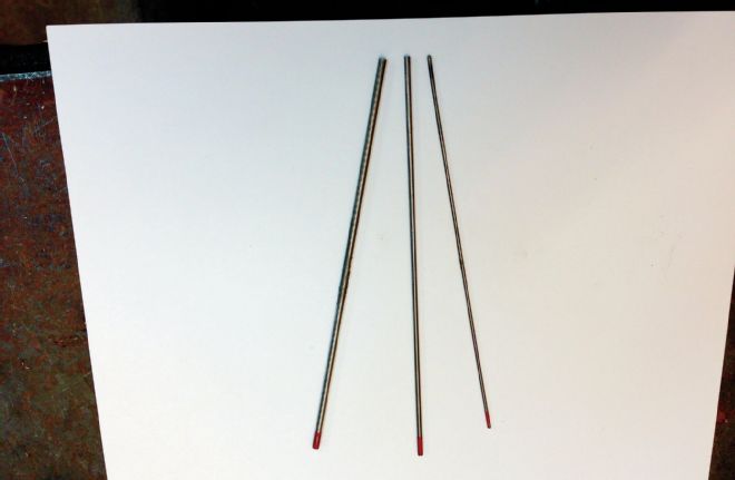
If the collet and collet body are sized by tungsten diameter, how do I know what tungsten diameter to select? It is actually quite simple. The diameter of the tungsten determines how much amperage it can take before it melts: a larger diameter tungsten equals more amperage.
You have to remember when welding using the AC mode (aluminum), the arc changes from electrode negative to electrode positive constantly, so more heat is put into the tungsten. Additionally, changing the AC balance will affect how much current the tungsten can take before it melts. If you run more cleaning (higher percentage electrode positive), then the amperage the tungsten can handle will decrease, because more cleaning puts more heat in the tungsten.
One of the mistakes I made in the past was trying to run 3⁄32-inch tungsten for too wide a variety of jobs. Using too large of a diameter tungsten for a given amperage causes erratic arc start, the arc is more likely to wander, and the arc will be harder to control. To see this firsthand, put a 1/16-inch tungsten in your torch, set your peak amperage to 200 amps, and gradually increase the amperage until you see the tungsten melt (it becomes white hot and starts to spit into the work). It is important to be able to identify problems.
So I select my tungsten based on amperage, but how do I know what amperage for a given thickness of material? A good rule of thumb is one amp per 0.001-inch. So if you had 18-gauge mild steel, whick is 0.048-inch thick, then about 50 amps would be a good starting point. However, this gets into how to set up your torch, so consult your user manual for your specific application.
The chart below is a great guide to selecting the correct diameter tungsten based on the welding amperage.
Tungsten Diameter .040-inch (1.0mm) 1/16-inch (1.6mm) 3/32-inch (2.4mm) 1/8-inch (3.2mm) Amperage - AC 20-40 30-100 60-160 140-230 Amperage - DC 15-50 50-130 80-200 130-250