I'm sure I'm preaching to the choir when I say that Total Cost Involved Engineering offers some of the most popular and highest-quality suspension kits and components in the aftermarket and are known for constantly developing new products for both the automotive and light truck aftermarket. I've used many of their products on my project cars and trucks over the years; in fact my current pickup project is equipped with both their street-rod style coilover IFS and rear four-bar coilover rear suspension assemblies as well.
A short time ago I heard through the grapevine that they were developing a new IFS system for '63-'72 C10 Chevrolet pickups and being the curious (nosey?) guy I am I gave 'em a call to see if I might be able to swing by their factory R&D center to see for myself (and hopefully share with you) what their newest classic pickup suspension design consisted of. As always they were more than happy to let me (and my camera) into the shop and invited me to watch one of these new systems being installed on a C10 chassis in real-time while I was at it.
Once I arrived I found that Total Cost Involved Engineering has a brand-new '63-'72 C10 Chevy bolt-on custom IFS equipped with RideTech coilover shocks and specifically engineered for standard street, autocross, and Pro Touring applications (for ½-ton trucks only). This new American-made front suspension product supports a 5/7-inch drop front/rear vehicle stance when used in conjunction with their new bolt-on Torque Arm rear suspension (which we'll be showing you in an upcoming issue).
The most exciting aspect of this new IFS system is the fact that it's a completely bolt-on assembly! That's right, now even those who don't own welding equipment or perhaps do, but just don't feel comfortable enough to attempt a project as important as front suspension and steering can now upgrade classic ½-ton pickups on their own in their home shop/garage.
So, rather than babbling on with info you can easily get by visiting the Total Cost Involved website (www.totalcostinvolved.com) let's cut to the chase and take a look at just how easily their bolt-on independent front suspension system is to install with nothing but a well-stocked toolbox, an electric drill, and your very own greasy mitts. CT
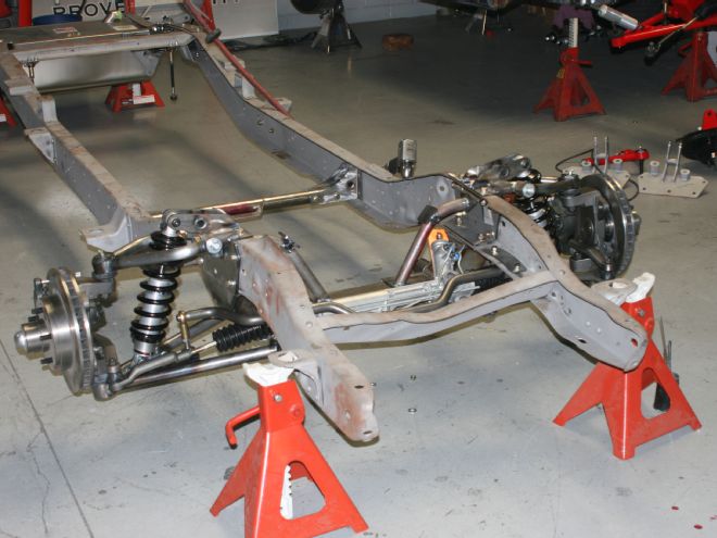
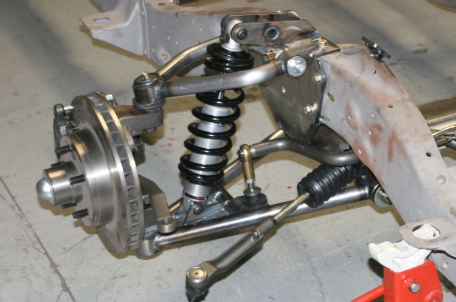
01 The new Total Cost Involved bolt-on IFS system is a great way for the classic truck enthusiast to upgrade their '63-'72 ½-ton pickup with a suspension/steering system that's just as at home on the freeway as it is on an autocross course. The fact that it's a completely bolt-on assembly makes it a great upgrade for the do-it-yourselfer who may not own a welder or who do but are not quite comfortable enough to perform a weld-in conversion on their own. The new 5-inch-drop bolt-on IFS kits feature TCI Engineering Modular Custom Truck Spindles, heavy-duty upper truck control arms, heavy-duty lower truck control arms, 5-inch-stroke single adjustable RideTech coilover shocks, powdercoated springs, small-block, big-block, and LS engine fitment, Energy Suspension polyurethane bushings, Moog upper and lower ball joints, a reinforced 3/16-inch-thick crossmember, complete rack-and-pinion assembly, one-piece lower control arms, a bolt-on sway bar, 12-inch vented rotors, and Big Bore caliper assemblies.
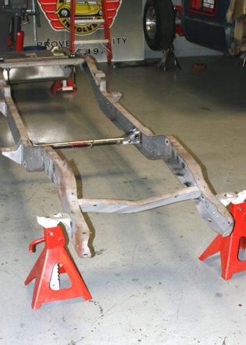
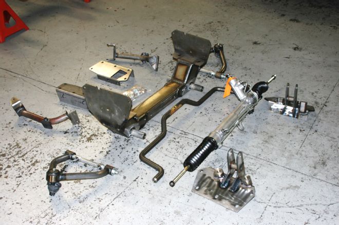
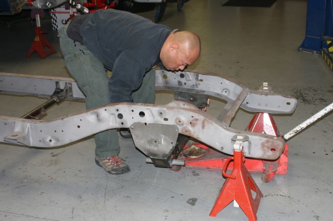
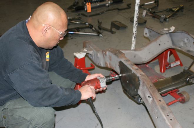
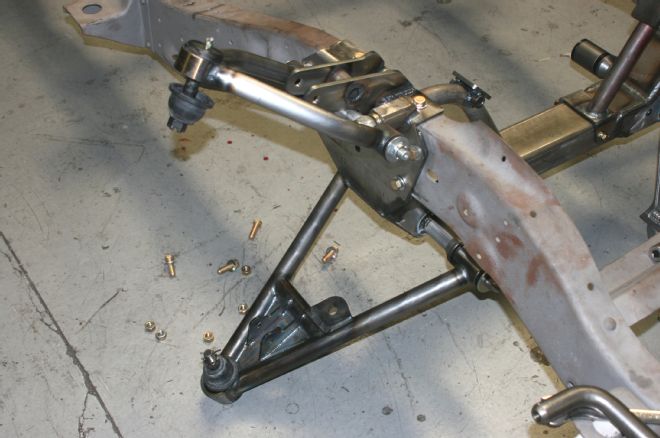
02-03 Installation is actually really straightforward and made simple with complete step-by-step instructions. In this case the install was performed on a bare frame to aid in clear photography, the install can be done with your front sheetmetal in place (with the engine and trans out), but totally exposing the front frame will make the job a heck of a lot easier. Here you can see the crossmember, the inner support plates, and the engine mount brackets. Once the front frame is accessible the first steps are unbolting and removing the original crossmember and suspension assembly. With that out of the way then remove the original front shock mounts and if so equipped, the front sway bar and brackets (in some cases the brackets are riveted in place so they'll need to be drilled out) and you'll be ready to begin installing your new IFS. Note: It's recommended that all new parts be mocked up (using standard nuts rather than the Nyloc nuts supplied in the kit) before painting or powdercoating.
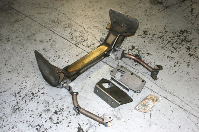
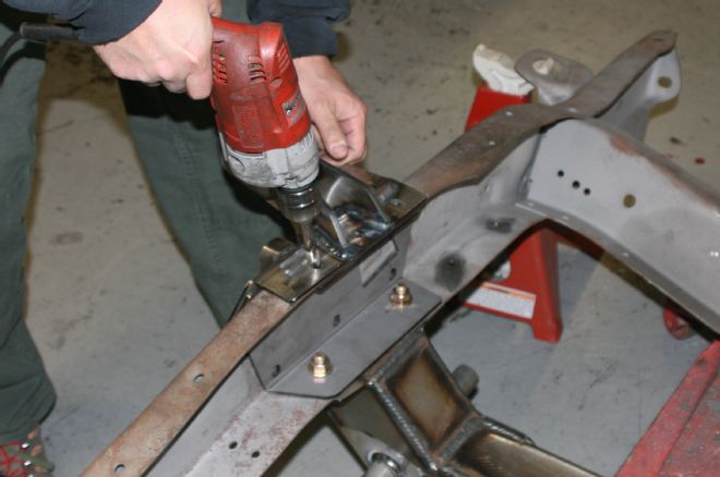
04 Place the new crossmember on a floorjack and lift it into place up against the bottom of the frame aligning the existing bolt holes on the frame with the holes in the crossmember (the framerails are tapered so the crossmember only fits in one way). Starting with the vertical holes in the bottom of both framerails insert the bolts through the matching holes in the crossmember and snug them up to hold the crossmember snuggly in place against the frame.
05 At this point use the remaining holes in the crossmember as a guide and drill the corresponding holes in the frame for the rest of the crossmember mounting bolts.
06 Next come the inner reinforcement plates. With the jack still holding the crossmember against the frame, remove the crossmember mounting bolts on one side (and loosen the other side's mounting bolts a bit) and slide one of the plates into place making sure that the cutout goes toward the front of the truck. Reinsert the bolts up through the bottom of the frame and the reinforcement plate and snug 'em up finger tight. Repeat the process on the opposite side and when all of the mounting holes in the frame, crossmember, and inner plates on both sides match up you're ready to pull it all apart and paint or powdercoat the components prior to beginning the final permanent installation. (We're going to skip the painting and proceed with the install with the bare metal components.)
07 The next step is adding the upper control arm brackets. The brackets fit over the outer crossmember mounting plates, so starting on one side, making sure the floorjack is still holding the crossmember in place, remove all the mounting bolts (see why we suggested using regular nuts rather than the Nylocs), and place one of the upper control arm brackets (with the higher control arm bung toward the front of the truck) directly over the outer crossmember mounting plate and reinsert all of the mounting bolts.
08 Using the control arm brackets as a guide, drill the three holes on the top of both of the framerails and then you're ready for the next step.
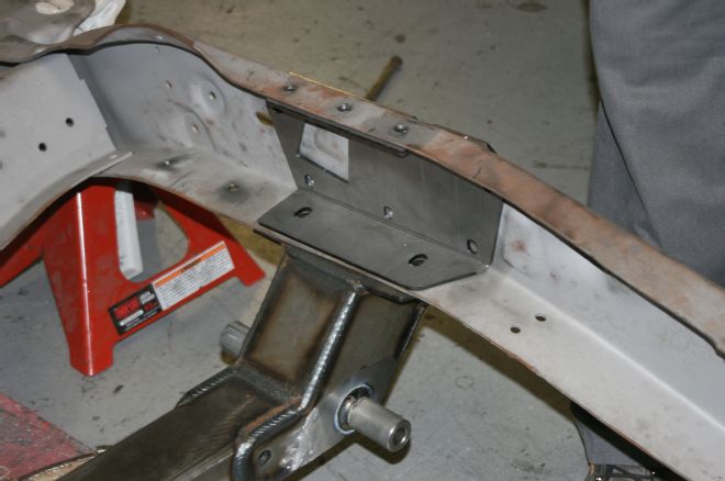
09 The engine mount brackets come next. One end of each fit over the crossmember (to be held by one horizontal bolt) and the tops under the top of the framerail and aligned with the front two mounting holes of the control arm bracket. (The engine mounts are right and left specific, make sure they align with the front two holes of the control arm bracket.) The bolts can now be inserted into the top three holes of the control arm plates and the horizontal lower bolts through the crossmember (from front to back). At this point all nuts and bolts can be fitted with Nylocs and tightened to spec (½-inch 85 lb-ft, 7/16-inch 70 lb-ft, and 3/8-inch to 45 lb-ft).
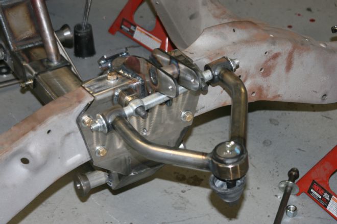
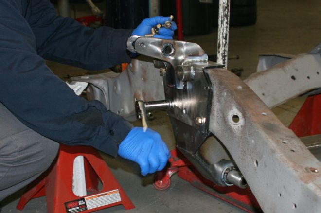
10 Next come the upper control arms. Start by installing the mounting studs in the bungs on the control arm brackets. Use thread-locking compound on the studs. Next, slide three flat washers onto each stud and slide the upper control arm onto the studs making sure that the control arms are mounted with the ball joint positioned toward the back of the truck. The three washers installed first will set the arms near zero camber. Add a flat washer to each and thread on the Nylocs and tighten, repeating the process on the opposite side.
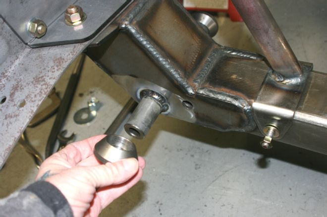
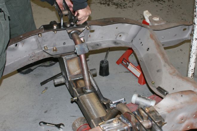
11-12 Next come the lower control arms. They are side specific so make sure the sway bar mounting bungs are toward the front of the truck with the ball joint stud facing up. Remove the shaft from the lower arms, place the tapered sleeves over the control arm pins on the crossmember, lube the control arm bushings, and then lift the control arms into place, and with the acorn nuts toward the front, slide the shafts through the arm tapered sleeves and crossmember. Add a washer and nut to each shaft and tighten 'em to 100 lb-ft.
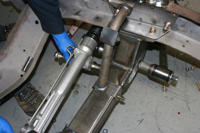

13-14 Next up is the rack-and-pinion. Before installation it is very important to make sure the rack-and-pinion is centered. The Total Cost Involved installation directions have specific instructions on how to accomplish this correctly. Install the mounting bolts and flat washers through the rack mounting holes and slide the machined spacers onto the backside of the rack. Install the rack onto the front of the crossmember and install the flat washers and Nyloc nuts on to the mounting bolts and tighten to 100 lb-ft. (FYI, the rack-and-pinion used in the kit are '89-'93 Thunderbird/Cougar and the tie rod ends ES3004R/L.)
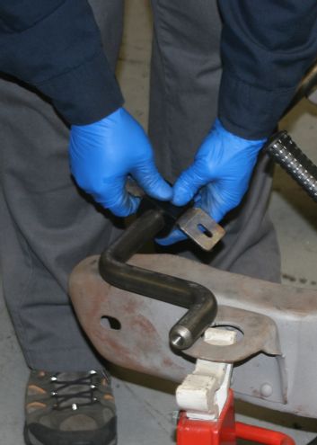
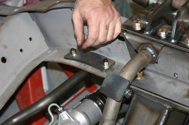
15-16 Sway bar installation comes next. The frame used here had been equipped with a sway bar originally so the sway bar saddles were attached using the original holes. In some instances the hole may have to be located, marked using the new saddles as guides, and drilled prior to installing the sway bar. Here the split sway bar bushings are lubed, attached to the sway bar, and slid into the mounting saddles. The sway bar was then bolted in place on the bottoms of the framerails forward of the rack-and-pinion.
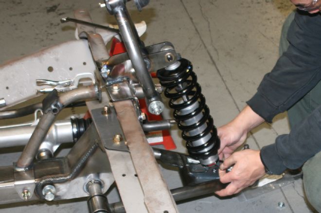
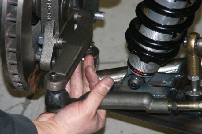
17 The adjustable RideTech coilover shocks were then installed. The RideTech shocks are both height and rebound adjustable. The locking collar on the threaded end of the body is locked by an Allen-head bolt that must be loosened before height adjustments are made and locked back down before being put under vehicle weight. The rebound adjustment knob is located at the top of the shock. To the left is soft and to the right stiff.
18 After the shocks were installed it was back to the rack-and-pinion and installing the tie rod ends. The lock nuts followed by the tie rod ends are threaded on far enough to reach zero-toe which is close enough to get the finished pickup to the alignment shop for exact alignment.
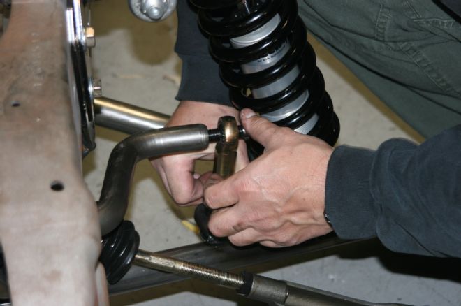
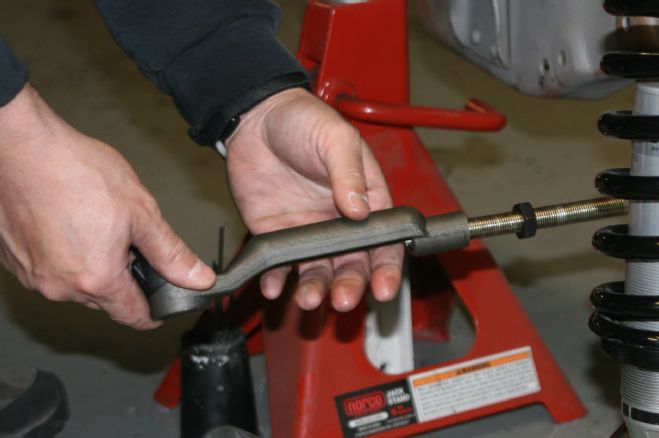
19 From the tie rod ends to the sway bar links. Assemble the links in accordance with the Total Cost Involved instruction sheets and then insert the links into the bungs on the forward portions of the lower control arms, making sure there's a bushing and washer above and below each bung. Thread a cap washer and Nyloc nut on each link just tight enough to compress the bushings to about half their thickness. Next, turn the Heim joint on the links so the holes line up with the holes in the end of the sway bar, install the button head bolts, and tighten 'em to 50 lb-ft.
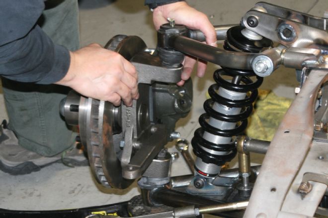
20 The spindle and brake assemblies are next. Total Cost Involved assemblies feature 12-inch rotors, Big-Bore calipers, and modular custom truck spindles all preassembled and ready to install. To orient the assemblies right and left just make sure the steering arms point toward the front of the truck. Position the spindle onto the lower ball joint being careful not to tear the ball joint boot and thread the castle-nut on finger tight. Align the upper spindle with the upper control arm ball joint stud and attach it while taking care not to tear the upper boot as well. Install the upper castle-nut and then repeat the process with the other spindle and brake assembly.
21-22 Finally, insert the tie rod end studs through the steering arms of both spindle and brake assemblies, and thread on the castle nuts.
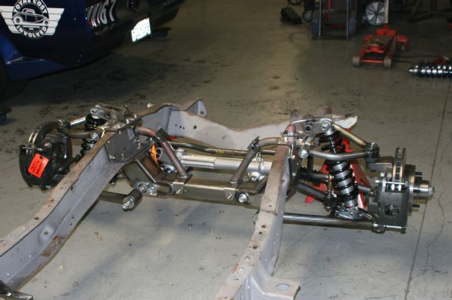
23 At this point all that's left is to tighten and/or recheck all the nuts and bolts, add cotter pins where required and step back and feast your eyes on the awesome IFS system you just installed all by yourself! Welder? We don't need no stinkin' welder! And there you have it, a great-handling bolt-on IFS system worthy of the Total Cost Involved name.