Last month's installment of our 60th Anniversary Speedway Motors Tribute T was fairly painless, as getting it to the rolling chassis stage was genuinely like building a 1:1 scale model kit, except we used nuts 'n' bolts instead of glue. This month we veered away from the kit ethos, as though Speedway Motors offers pre-bent brake line kits for some of its other T kits, as of this writing, they don't offer one for the Tribute T. They can, however, supply lengths of straight 3/16-inch brake tubing, flex hoses, and all the fittings and line clamps required, along with the tools needed, should this be your first time.
It's easy to get confused when bending brake lines, but plan it out and go slowly and it can actually be enjoyable. We started at the master cylinder, worked our way to the adjustable proportioning valve, plumbed back to the rearend, and then forward to the front brakes. We added residual valves in the lines to prevent fluid bleeding back to the master cylinder, as it is mounted lower than the brakes. We used electrical tape to hold the tubing to the chassis until we'd completed each section of the system, then drilled and tapped the framerails to accept 10-32-inch Allen headed stainless bolts and stainless line clamps.
We also painted and installed the Blueprint Engines 350ci Chevy small-block and B&M TH350 transmission this month. Our chassis was supplied with mounts for an SBC, which eliminated any fabrication or welding (gotta say, that aspect of building a “kit car” sure is nice!). We used Eastwood's new two-part aerosol primer once we'd prepped the engine block, heads, and oil pan, followed by single-stage Ford Wimbledon White. Naturally we took the necessary respiratory precautions required when using such products. Hey, this thing's beginning to look like a car!
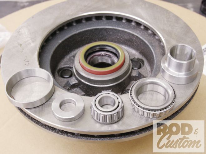 1. To fit the disc brakes supplied by Speedway to the early Ford-style spindles, a different inner bearing race has to be installed (and the old one removed) along with a new seal. New bearings are supplied.
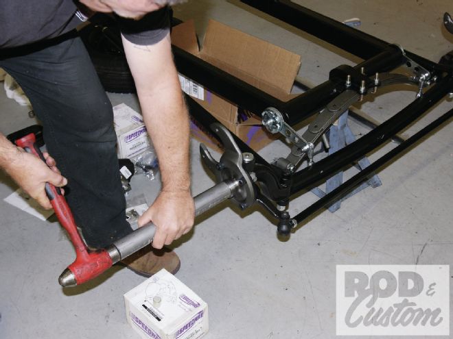 2. The "top hat"–shaped item seen on the right in the previous picture is an adapter to enable the new inner bearing to work with the Ford-style spindles. It has to be pressed into place. As we’d already installed the spindles, we used a length of thick wall steel tube and a mallet to drift it home.
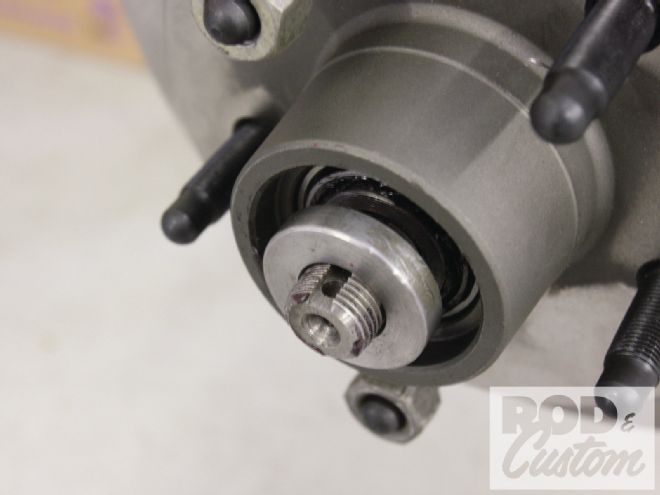 3. Finally, with the rotor in place and the bearings packed with grease, this spacer has to be used to shim out the spindle nut so the cotter pin can still be used. Note the caliper mounting brackets and steering arms were installed prior to the rotor being fitted.
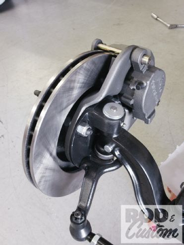 4. The T calipers were installed next, after they’d been painted using Eastwood’s Spray Gray, for an “as-cast” finish.
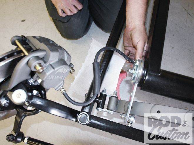 5. Prior to determining where the flex hose brackets would locate on the frame, the hoses were held in place while the steering was turned lock to lock …
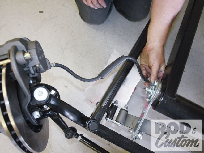 6. ...to ensure the hoses wouldn’t foul or rub against any other components. The location shown proved to be ideal: underneath the chassis just behind the friction shocks.
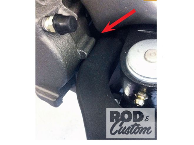 7. One small problem we encountered, apparently because we mounted our calipers behind the spindle and not in front, was this nub on the driver side caliper, which fouled the steering arm. We simply ground it down for clearance.
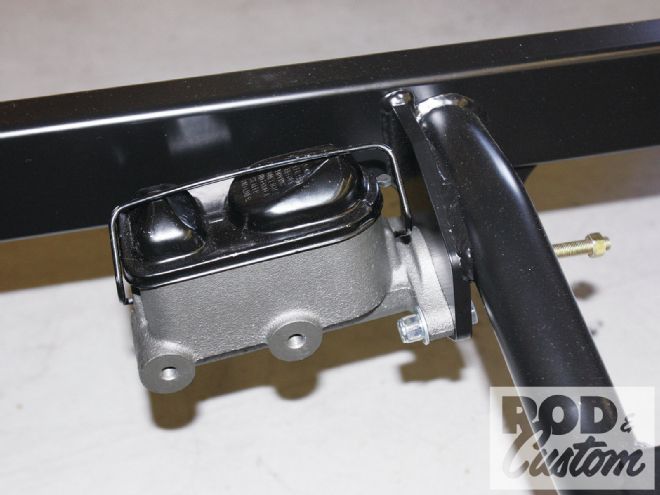 8. Also painted Spray Gray, the master cylinder bolts to this pre-welded bracket on the transmission crossmember.
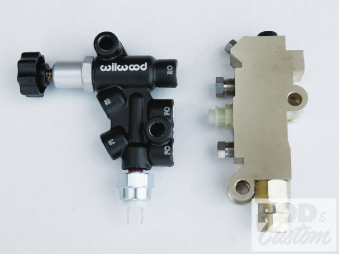 9. Speedway supplied this Wilwood adjustable proportioning valve, seen here alongside a regular proportioning valve for comparison.
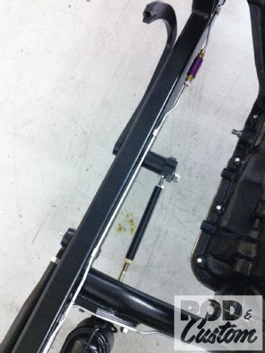
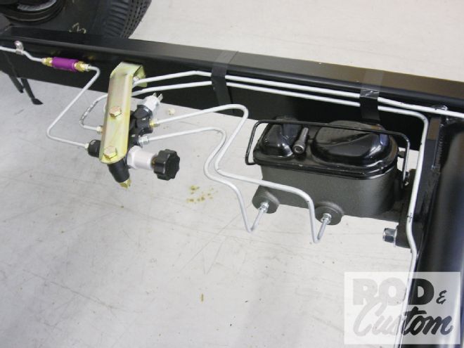 10. While adjustable valves are usually mounted with the knob facing downward, once the brake lines are plumbed into it, it would hang down way below the chassis, so we elected to mount it horizontally, as shown. We used a bracket leftover from another project, which mounts a regular proportioning valve to the master cylinder. The chassis was drilled and tapped to accept a 3/8-inch bolt. Note also how we used electrical tape to hold the brake lines in place prior to installing line clamps.
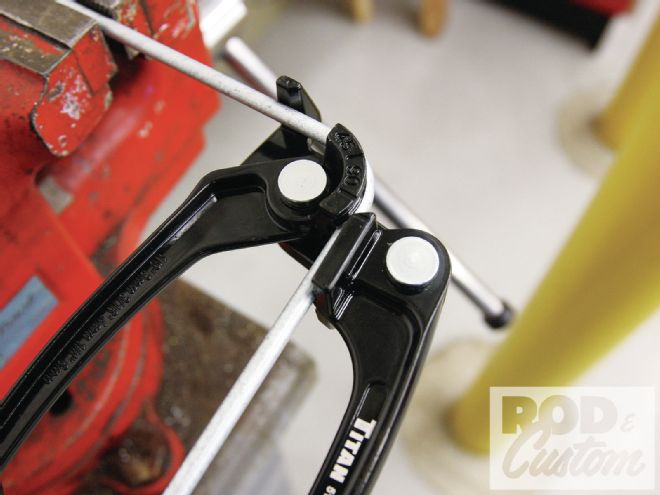
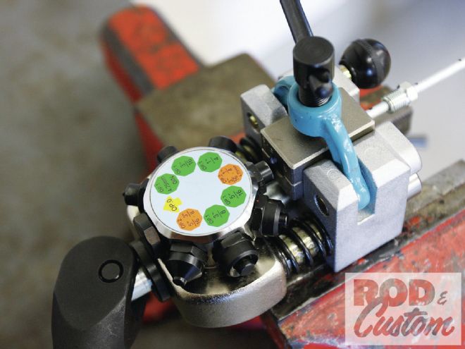 11. Eastwood sells this tube flaring tool, which is the best we have ever used, period. It performs the two steps to produce an inverted flare without having to remove the tubing from the clamp at all. It’s virtually foolproof, and is a huge time saver. Definitely recommended!
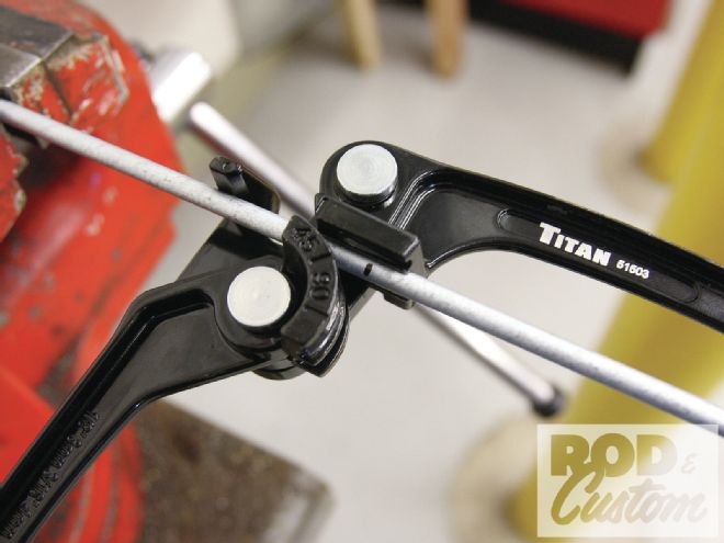 12. Speedway supplied several straight lengths of 3/16-inch brake tubing, as well as all the fittings and residual valves required.
 13. Speedway also supplied this neat tube-bending tool, ideal for forming tight radii. The Sharpie mark on the tube relates to where the outside of the bend is required.
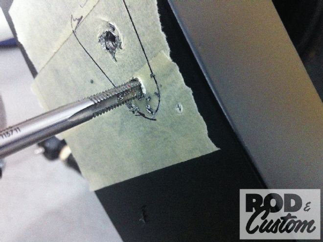 14. The flex hose brackets and line clamps were attached to the chassis by drilling and tapping to accept 10-32-inch Allen headed stainless bolts. Masking tape prevents accidentally damaging the powdercoat, plus allowed us to mark the position of the brackets prior to center punching the drill marks.
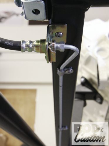
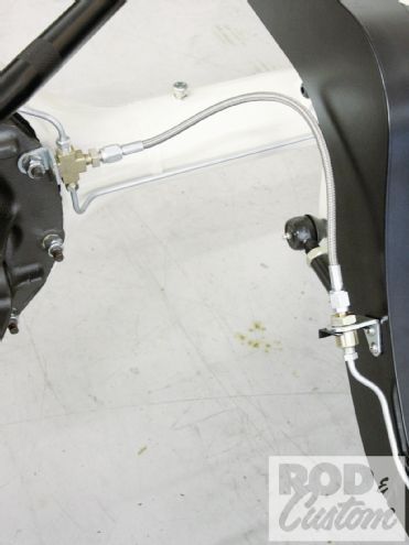 15. To the right you can see the bracket we were mounting in the previous picture, while on the left you can see the T-piece connecting the flex hose to the rearend brake lines. We ordered the T-piece with integral mount, and used one of the third-member bolts to attach it.
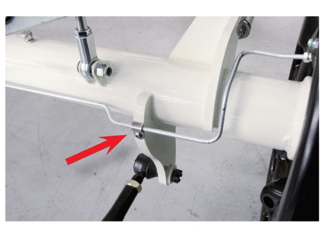 16. As our rearend was already painted and assembled, we were reluctant to drill and tap the casing for line clamps, then hit on the idea of tapping the edge of the 1/2-inch-thick lower suspension bracket.
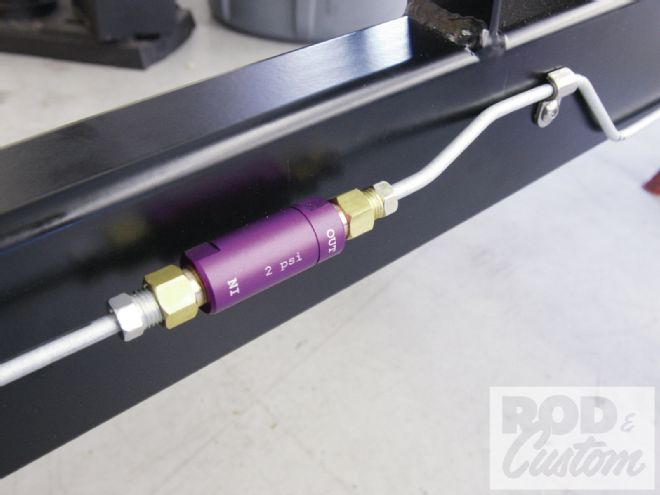 17. As our master cylinder is mounted below all four brake cylinders, we included residual valves in the brake lines to prevent fluid bleeding back to the master. We used 2-psi valves in the front brake lines, and a 10-psi valve in the rear.
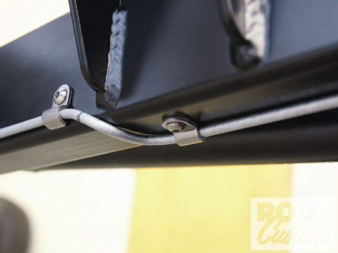 18. We ran all the brake lines inside the framerails, except for the front section of the chassis. As the T has a portion of frame with both sides visible in front of the grille, we didn’t want the lines visible, so we kicked them under the ’rails at the engine mount on each side, and ran them underneath the chassis …
 19. ...to the front flex hose brackets, like so. Now we just have to remember not to put jackstands under the front ’rails!
 20. The Speedway brake pedal passes through a bushing in the driver side chassis, offering two positions for the master cylinder pushrod, and hence two variations of pedal firmness/travel. The extension rod for the pushrod is required for the Tribute T kit, though not for Speedway’s other Ts.
 21. With our brake system installation underway, we also could install the Blueprint engine (it’s way harder to drill and tap the line clamp holes and run lines with the engine and trans in the way!), but first we had to change its color to match our rearend.
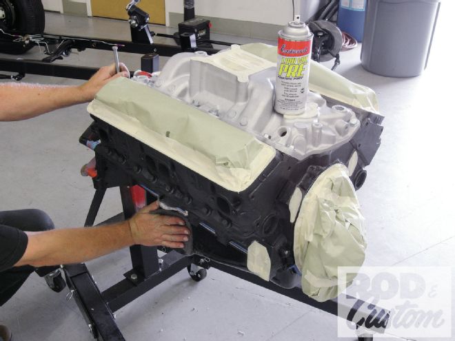 22. With the valve covers and plugs in the intake removed; fuel and water pump, thermostat, carburetor and distributor bosses, and timing cover masked; we prepped the block, heads, intake, and pan using gray Scotch-Brite and Eastwood’s PRE paint prep.
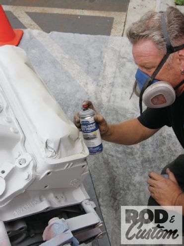 23. Ensuring we used a respirator mask, we opted to use Eastwood’s new Aero-Spray Epoxy Primer. This is a two-component primer in an aerosol, and should be treated in the same manner as regular single-stage paint from a spray gun.
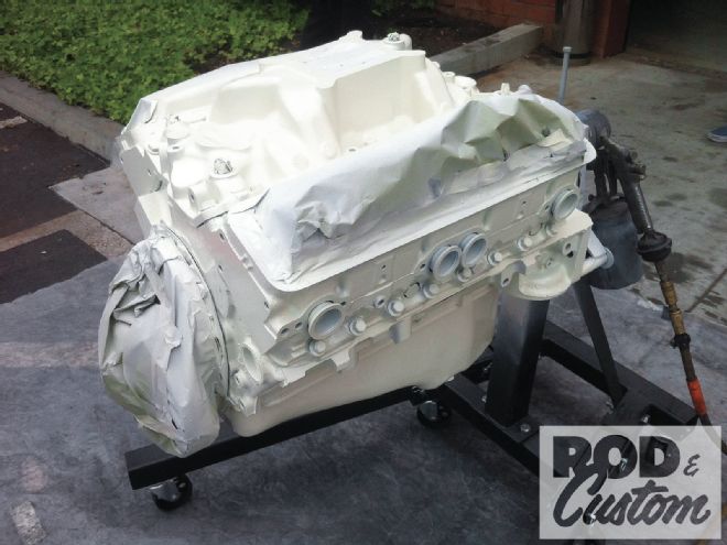 24. Considering the surface of the block wasn’t exactly smooth, and we weren’t going to sand the primer, we opted to apply the Ford Wimbledon White single-stage wet-on-wet directly over the primer once it had flashed off.
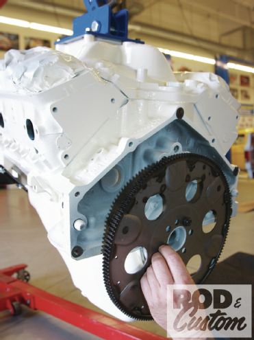 25. The following day, with the paint dry, we installed the flexplate on the crankshaft, using the bolts supplied …
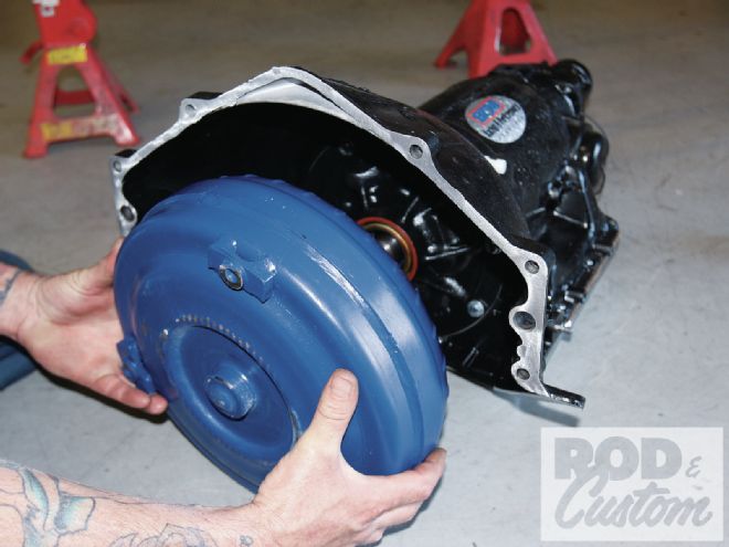 26. ...then put ATF in the torque converter and installed it in the B&M TH350 transmission, ensuring it was pushed all the way “home”.
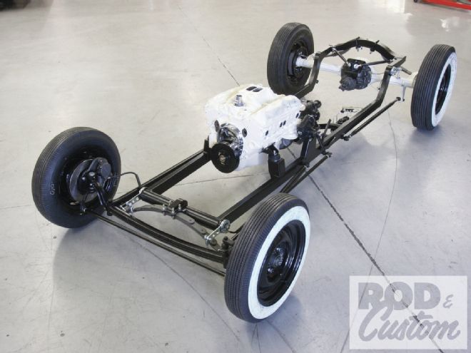
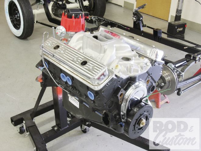
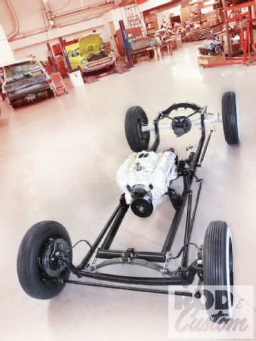 27. With the engine and transmission mounted in the chassis, using engine mounts specific to this kit and universal rubber biscuit-type mounts, and the brakes plumbed, we’re well on the way to completing the Tribute T.