When Ford designed the F-100 they did everything right, with the possible exception of not getting it close enough to the ground. For years the cure for that was to install a dropped axle, but while that reduced the truck’s altitude, its attitude could suffer—bumpsteer often accompanied the installation of a modified I-beam. With the introduction of Mustang II independent front suspension kits CUSTOM CLASSIC TRUCK fans found they could have it all, a better ride, improved handling and that cool, in the weeds look.
Over the years these kits have been refined and improved—in most cases the OEM strut rods have been deleted, tubular A-frames have been substituted for the stamped steel variety, and bigger disc brakes are used. But some things remain the same—the spindles are reproductions based on the Mustang II. At one time criticized because they came off a small car, the fact is the spindle pin and wheel bearings are bigger than those found on many GM clips (such as the Nova) that are common swaps.
Jake Brazille has been collecting 1956 F-100 parts for quite some time and when the pile got big enough he decided to build a pickup from the ground up. For front suspension Jake chose a weld-in kit from Bob’s F-100 Parts, it came complete with a power rack-and-pinion, disc brakes, and Aldan coilovers.
The owner of Bob’s F-100 Parts, Bob Carlisle, started his love affair with Ford trucks at the tender age of 15 with a 1953 F-100 powered by a triple-deuce-equipped 312. Later in life, after becoming a journeyman mechanic, Bob opened his own shop and worked on everything from Cobras to gyrocopters, but it was a string of Ford pickups that set his future course. When the business where Bob was buying truck parts came up for sale the die was cast. Today Bob’s F-100 Parts carries a complete line of new and used parts for 1948-1978 Ford trucks and a shop that cranks out turn-key customs and restorations.
Bob’s offers a variety of front suspension options including Volare clips, bolt-in kits, and weld-ins as shown here. While all work well Jake chose the latter because of the clean look. In terms of installation, the Bob’s weld-in suspension is self contained, that is to say all the components attach to the supplied crossmember, so it’s simply a matter of getting it in the frame square and centering the wheels in the fender openings.
Speaking of which, our pet peeve is tires that are too far back in the openings and with F-100s if you rely on the original axle centerline that’s usually what happens. So, even though it’s extra work, we always check the relationship before doing the final welding by assembling the suspension and hanging the fenders. Then we use a string looped over the spindle to make sure the spacing at the widest point is the same in front of and behind the tire. It’s not scientific, but it works. Once we’re happy with the tires’ location everything comes apart for final welding. Follow along and get the lowdown on gaining independence.
 1. Bob’s F-100 Parts offers a variety of IFS systems for Ford trucks—this is the weld-in version.
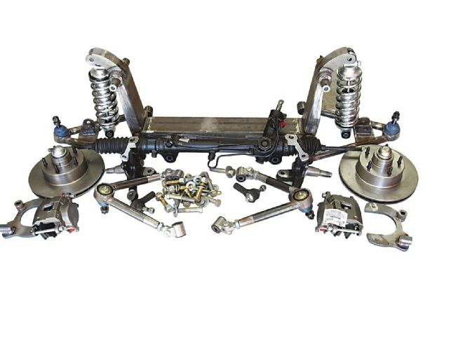 2. Everything necessary for installation is included in the kit. We opted for Aldan coilovers and GM metric calipers.
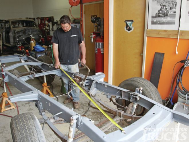 3. With the frame leveled on jackstands, Jake Brazille takes some measurements to ensure the frame is square; cross measured it was within 1⁄16 inch.
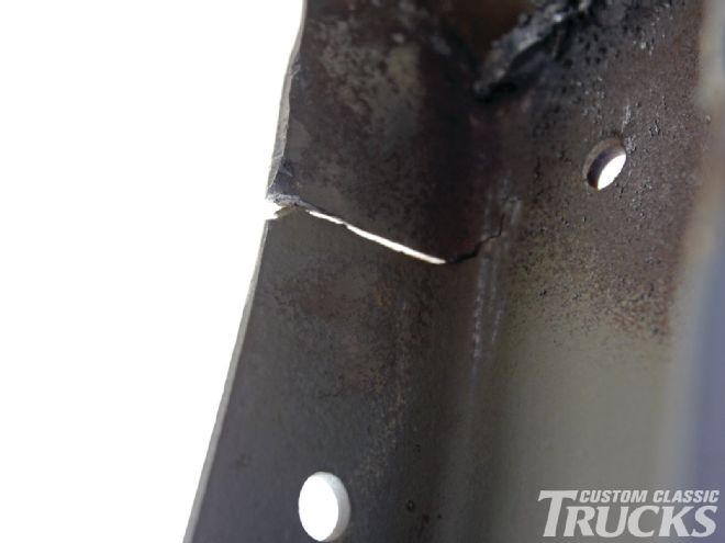 4. While the frame was good dimensionally, there were other issues. After removing the poorly designed motor mounts that had been added, cracks in the ’rails were found.
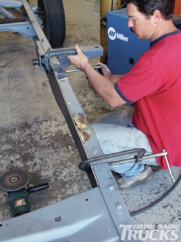
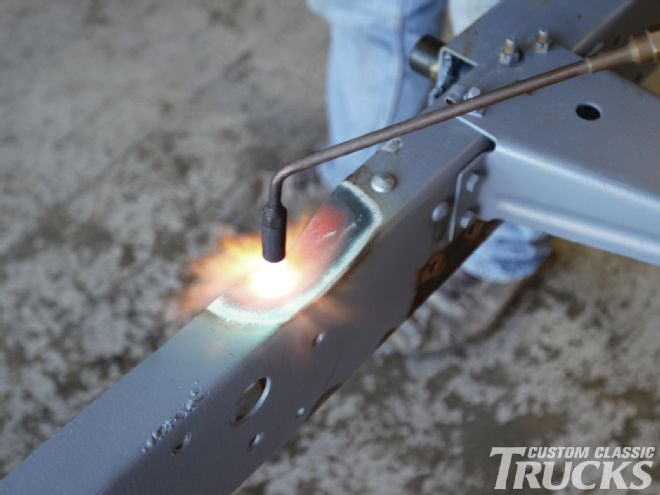 5. The stock rails have a “dip” in the top flange behind the steering gear—we decided to straighten it with the help of a rosebud.
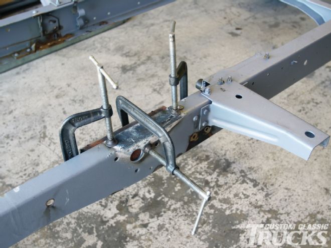 6. With the ’rail heated we used a chunk of heavy-wall tubing and clamps to straighten it.
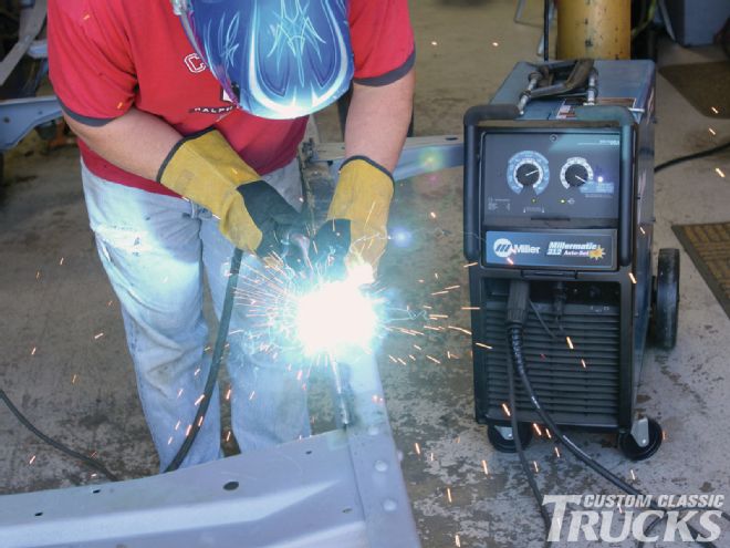
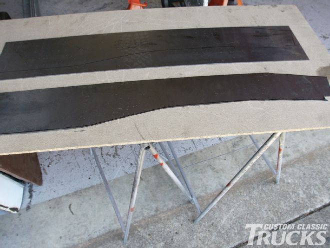 7. After repairing the cracks in the ’rails, we elected to box the frame from the front crossmember to the front cab mount.
 8. To provide penetration and allow for grinding, the edges of the frame’s flanges were ground at an angle. The boxing plates were then clamped in place.
 9. For now, just the front portion of the frame was boxed. Additional boxing plates will be added when the transmission crossmember is installed.
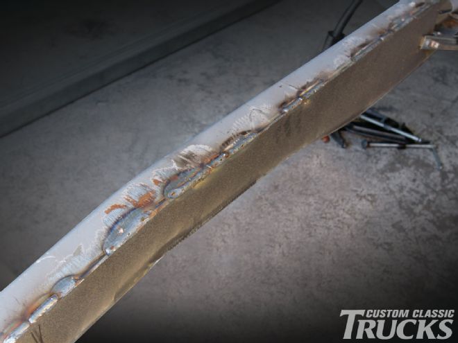 10. Skipping from side to side, short welds were made until the plates were welded entirely.
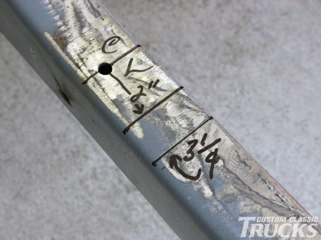 11. The original bumpstop holes were used as the centerline of the axle. The 2-inch mark represents the edge of the new crossmember. We moved it ahead an additional 1¼ inches.
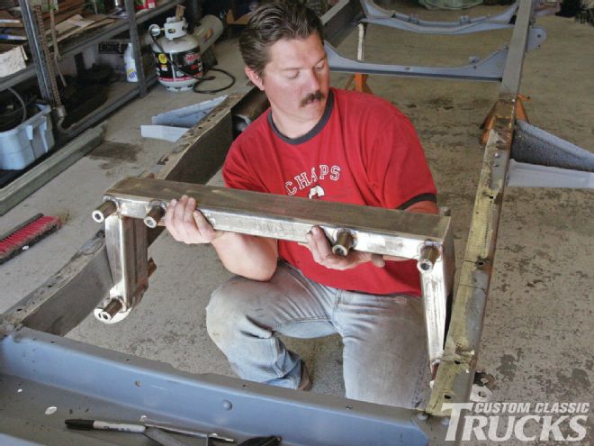 12. With the frame upside down, Jake checked the fit of the new crossmember.
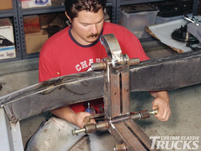 13. The crossmember was tacked in place and then we began assembling the suspension by installing the lower A-frames.
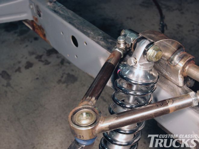
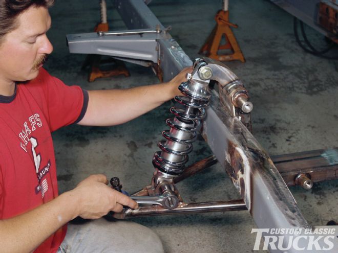 14. Next came the installation of the Aldan coilovers. Note the compression damping adjustment at the top of the shock.
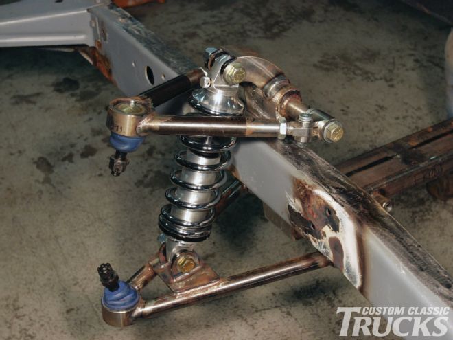 15. With the upper A-frames installed we were close to completion. Screw-in ball joints are used top and bottom.
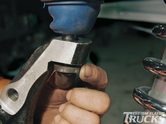
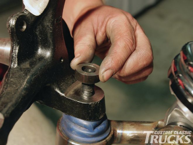 16. The bottom ball joint studs require the addition of the included spacer.
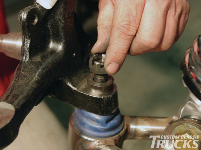 17. With the spacer installed, the slots in the castellated nut align properly with the hole in the stud for a cotter pin.
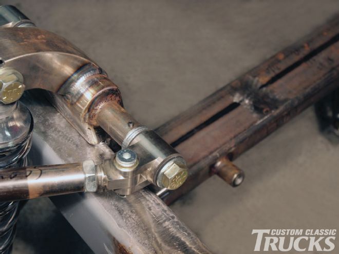
 18. All four A-frames are made from heavy-wall DOM tubing. Note how the crossmember fits over the top of the framerail.
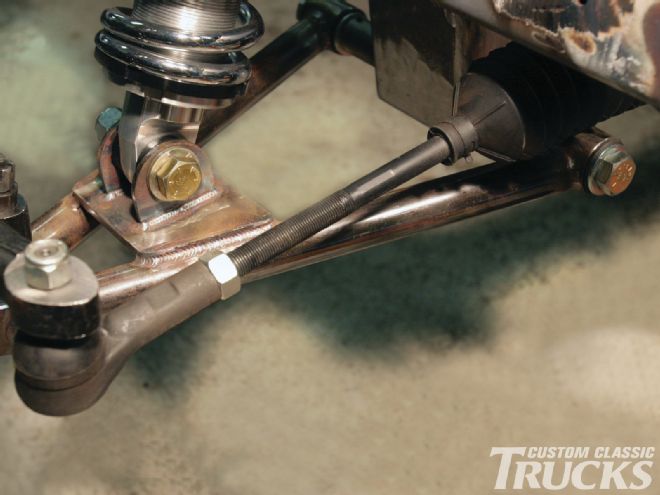
 19. Caster and camber changes are made with adjustable links on the upper A-frames. Note the use of all Grade-8 hardware and the setscrew to lock the attachment bolt in place.
 20. Toe adjustments are made at the outer tie-rod ends. Once the alignment is set, the locknuts are tightened.
 21. As with the bottom ball joint the upper requires a spacer washer, however, it is thinner.
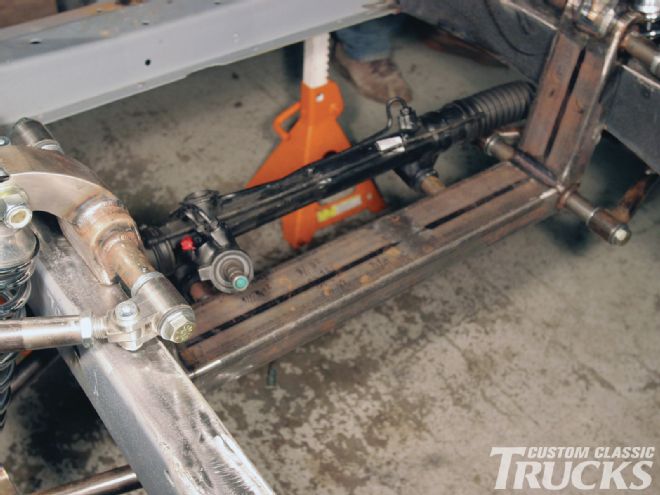 22. Thanks to the position of the rack-and-pinion’s steering shaft, just about any engine should fit without steering shaft interference.
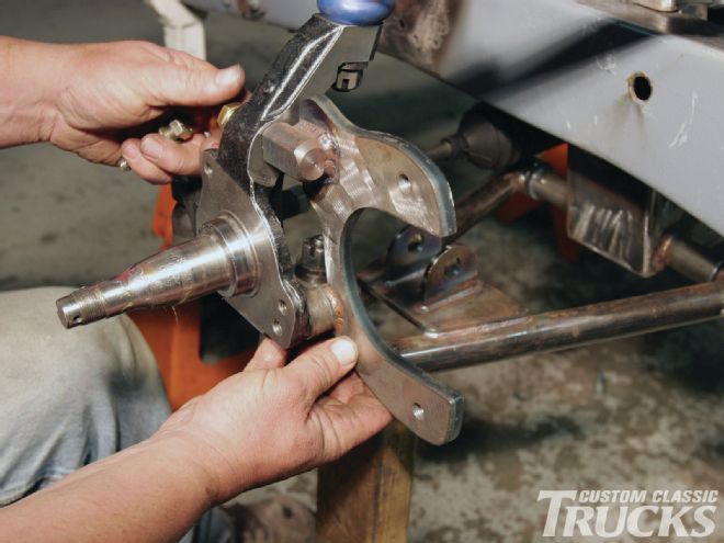 23. Included in the kit are mounts that allow the use of GM calipers on the Mustang II-style spindles.
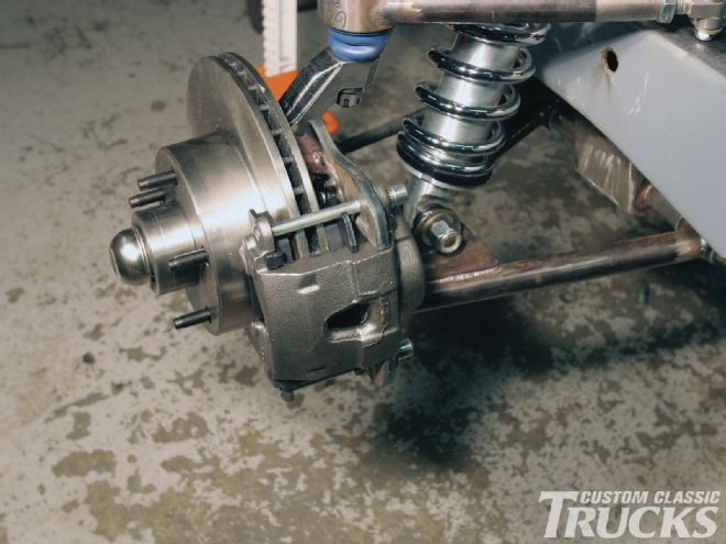 24. Vented rotors and GM metric calipers will supply plenty of stopping power.
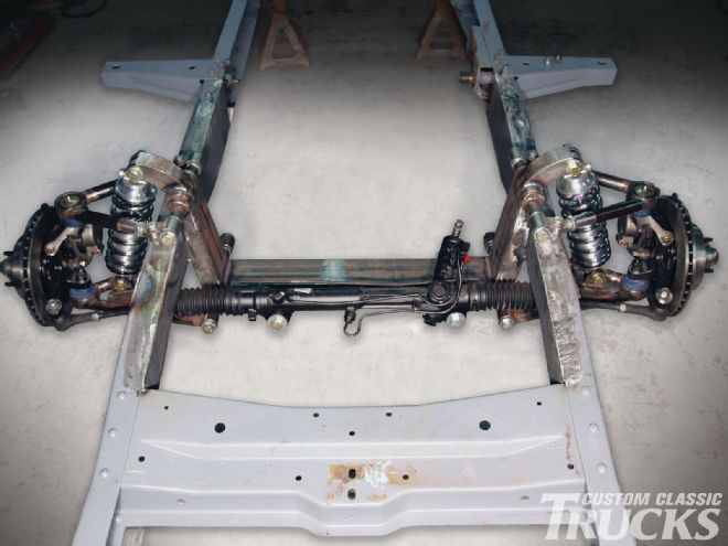
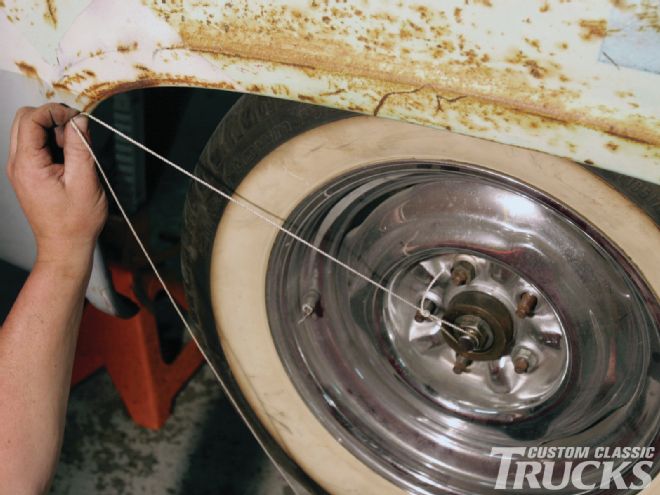 25. Here’s the reason the crossmember was tack welded, we wanted to make sure the wheels were centered in the fenders. After using a string to verify the spacing was the same front and rear, the crossmember was welded in place.