
Few driveline components have reached the legendary status of the 9-inch Ford rearend. As a result, it’s not unusual to find one under the tail end of almost anything with wheels, including Chevy pickups. The main reasons given are strength, the wide range of gear ratios, and the ability to change center sections easily. But truth be told, is replacing a GM rearend with a Ford really necessary? Let’s look at some of the differences.
In 1970 GM began producing the 8.5-inch rearend. Often referred to as the “corporate 10-bolt” because it can be found under almost every GM vehicle with the exception of Cadillac, the 8.5 reference indicates the diameter of the ring gear. These rearends are the Salisbury style, which means that the differential assembly mounts inside the integral center section of the axle housing.
One of the reasons often given for installing a Ford 9-inch is that they are the Hotchkiss style, which means the ring, pinion, and differential assembly are removable, so gear ratio changes are quick and easy. But unless you’re driving cross-country, then running at the drags, and later heading to Bonneville, the need for frequent gear ratio changes isn’t usually a consideration. What is worth considering is the difference in efficiency between the two. The Chevy rearend has a less severe hypoid angle because the pinion gear is closer to the centerline of the ring gear than the Ford’s. The result is the Ford design is slightly stronger, while GM is more efficient consuming approximately 3½-percent less horsepower due to reduced friction—and that lowers lubricant temperatures as well.
As far as gearing options, there are many more for the Ford as the ratio options increase/decrease by small amounts. However, there are plenty of options for the 8.5 GM, particularly for street applications.
Another common criticism of the 8.5 is that the axles are retained by C-clips inside the differential case and a broken axle can result in the wheel leaving the truck if a shaft snaps. While that is true, consider the 9-inch may have 28- or 31-spline axles and the 8.5 has 30-spline axles—breaking an 8.5 axle on a street-driven truck is unlikely. For those concerned with the C-clips, there are devices to alleviate any fears—C-clip eliminator kits or alloy axles are common used. And if you’re considering a disc brake installation you get a two-fer, better stoppers, and in the event of a failed axle, the caliper keeps the rotor captured, and as a result the wheel.
No conversation about rearends of any sort is complete without a look at the differential. With a standard differential, as the truck is going down the road in a straight line, power from the ring gear is delivered through the case and spider gears to the side gears on the axles. When the side gears are both turning the same speed the spiders remain stationary on their shaft. But when the truck goes around a corner, or one wheel loses traction, the wheels turn at different speeds and spider gears compensate by spinning their shaft. That’s how one wheel can turn faster than the other when turning a corner and also why all the power goes to the wheel without traction.
What are called traction-enhancing differentials fall into two categories: locking and limited slip. Locking differentials are great for traction, but lousy to live with on the street. While they unlock when going around corners, the action can be abrupt making the truck feel slightly twitchy when cornering.
A better alternative for street-driven trucks is a limited-slip differential. These come in various designs, but all work in a similar manner. When torque is applied to the differential and both wheels have traction, the clutch packs clamp the side gears to the differential case, keeping one tire from going up in smoke. This clamping action is directly related to the torque being applied—more torque means higher clamping force. However, when it comes time to turn a corner the clutch discs allow the slippage necessary to allow the axles/wheels to turn at different speeds.
A variation on the limited-slip theme is the gear type, like the Detroit Truetrac. Rather than clutch plates, these use worm gears that are forced away from each other. This action clamps the axle to the differential case. If one of the tires loses traction, the friction between the worm gears and the case is reduced; power to that wheel is reduced. In operation, limited-slip rearends are relatively seamless, they’re quiet and smooth and you’ll never know they’re there until you need them.
Faced with the repair, replacement or the substitution of a 9-inch for a tired rearend under an 1985 Chevy pickup we decided to stick with the original 8.5 assembly. We wanted someone who really knew their way around a rearend, so we turned to John at J&S Gear Company in Huntington Beach, California, to have it rebuilt. In business since 1957, J&S specializes in street rods, muscle cars, and trucks and they have lots of experience with the 8.5.
Armed with parts from Summit Racing, including a 3.42:1 ring and pinion set (SUM-741002); installation kit (RMG-8310211); Detroit Truetrac differential (DTL-912A556) and a pair of axles from Moser Engineering (A3079GMTK), John went about making our 8.5 better than new. Here’s how he did it.
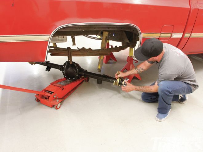 1. Freshened up inside and out, our trusty 8.5 rearend is ready for Jason Scudellari, head wrench and manager of Source Interlink Media Tech Center, to wrestle it back in place. Note the brackets for the disc brakes to come. John at J&S Gear made sure the exterior of our new 10-bolt was as detailed as the interior by degreasing and painting the entire assembly before it left his shop.
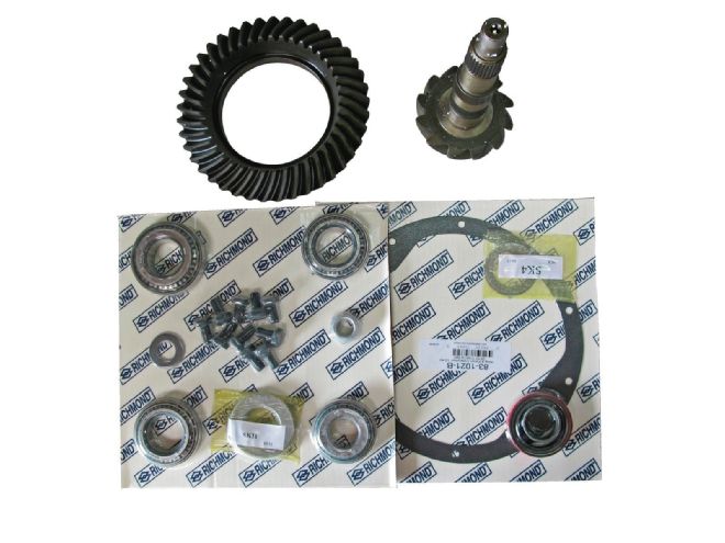 2. Summit can supply all the parts necessary to make an 8.5 better than new. There are a variety of ratios available, GM offered gear sets ranging from 2.40:1 to 4.10:1.
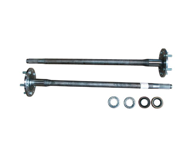 3. High-strength axles, such as these from Moser Engineering (#A3079GMTK), are a wise update. Axle wear can be an issue as the shafts act as an inner wheel bearing race and are in direct contact with rollers.
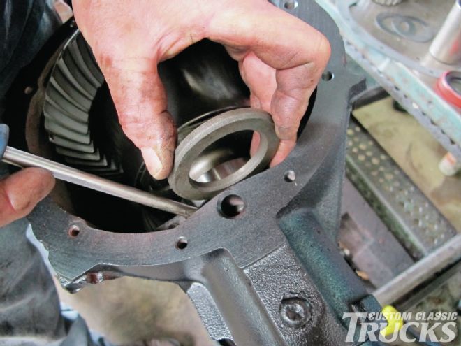
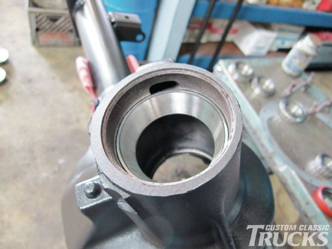 4-5. After disassembly and cleaning, the housing and axle tubes are inspected thoroughly, then new races for the pinion gear are installed.
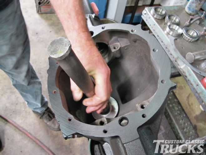
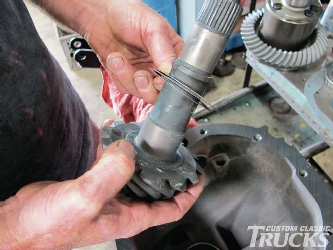 6. A critical step is setting pinion depth, it’s determined by shims between the gear and inner bearing.
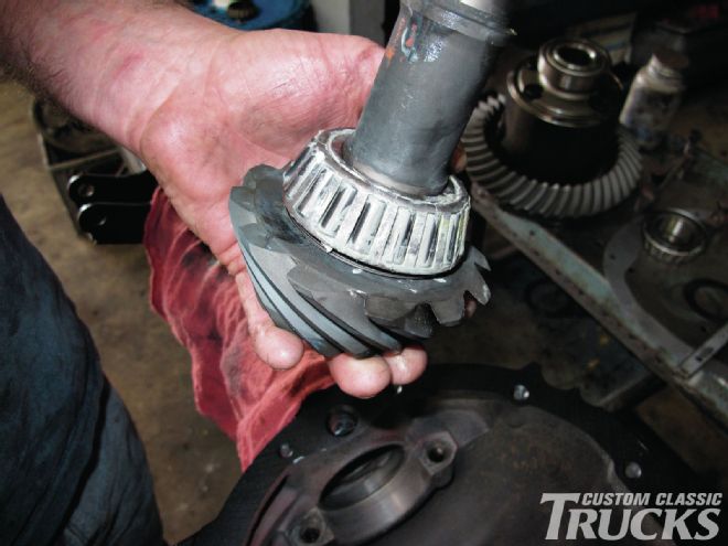 7. With the shims in place the bearing is installed. Factory measurements engraved on the pinion gear and a depth gauge is normally used to determine the shims necessary. John relies on experience.
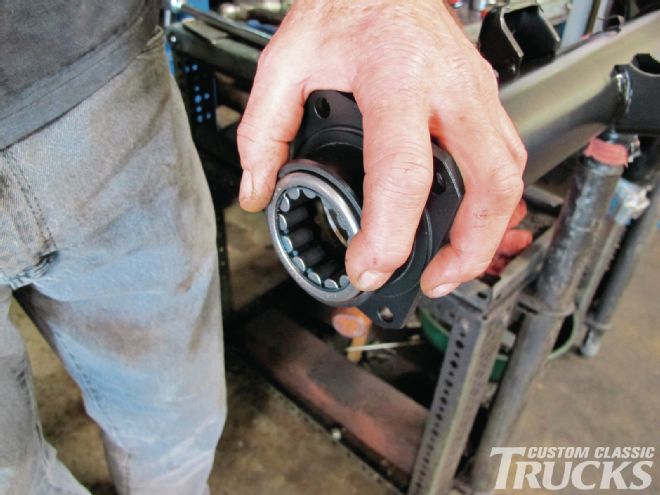
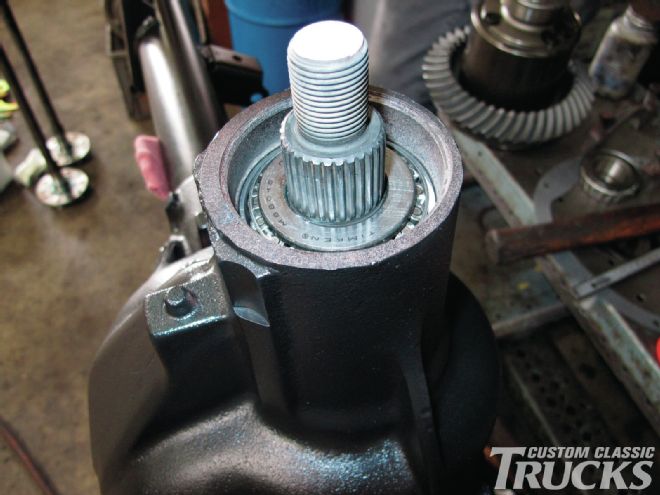 8. Once the pinion is in place the front bearing can be installed followed by the seal and U-joint yoke.
 9. Preload on the bearings is established by tightening the retaining nut until 25 in-lb is required to turn the pinion.
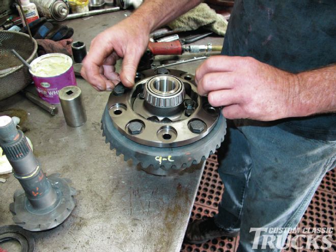 10. The ring gear is secured to the differential case with 10 bolts—be aware they have left-hand threads. John applied thread locker before putting them in place.
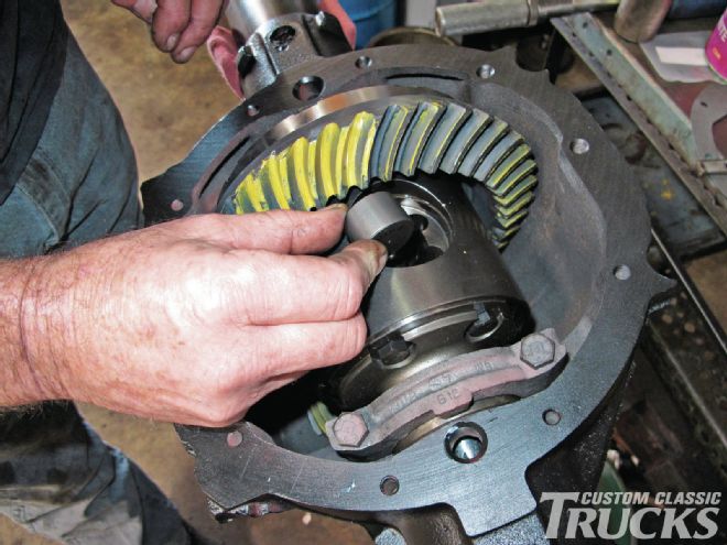
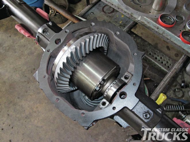 11. When the differential assembly is initially placed in the axle housing, it’s a loose fit as evidenced by the bearing not seated in the race.
 12. Shims not only take up the space, they establish the ring and pinion backlash—a .002-inch change in the shims makes a .001-inch change in backlash.
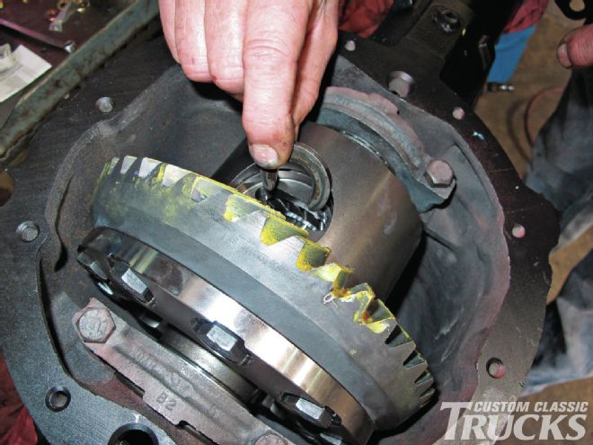
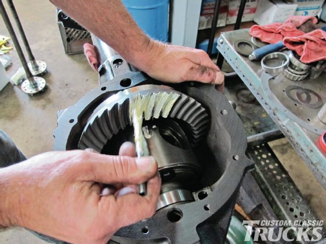 13. The time-honored procedure for checking pinion depth. The ring gear is painted with a marking compound—the gears are then rotated and the contact area can be seen
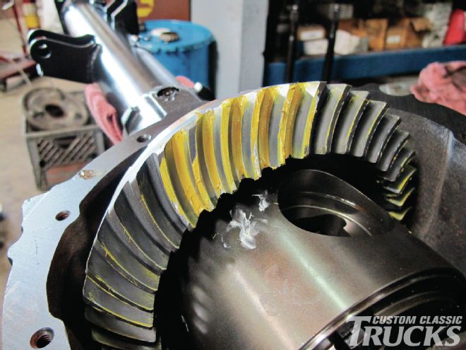 14. The drive pattern (on the left side of the tooth) should be centered on the tooth. The coast pattern should be centered on the tooth, but may be slightly toward the toe. John was right on the money.
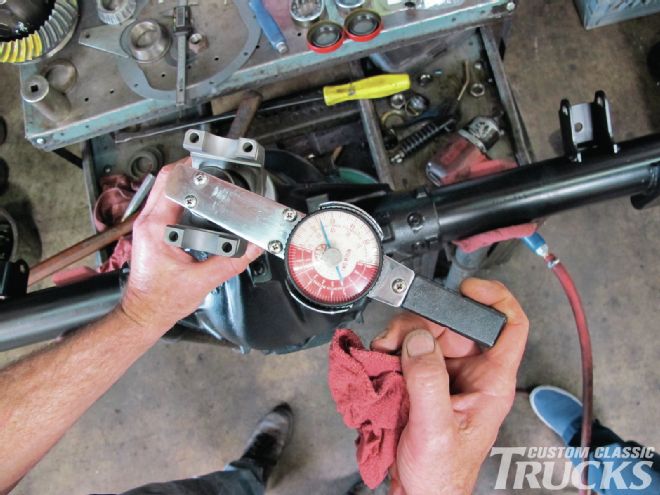
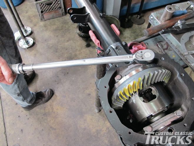 15. John sticks with all GM’s torque specifications for all the fasteners. With the bearing caps tightened, the next step is to measure backlash.
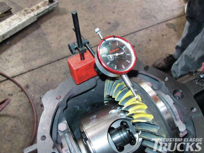 16. Factory specs for backlash, or play between the ring and pinion gears is .004 to .008 inch. John goes in the middle at .006 inch.
 17. Always recommended are new axle bearings. Here it can be seen that the bearing lacks an inner race.
 18. With the axles installed, the C-clips are put in place—the axles are pulled away from the center section slightly which seats the retainers in recesses in the case.
 19. This thrust block goes between the axles and keeps the C-clips seated. The block is held in place by a special retainer.
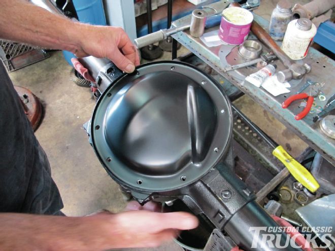 20. With a new gasket, the cover goes in place. The 8.5 is identifiable by a 10-bolt cover, and the squared lugs at the bottom of the housing (arrows).
Sources
J&S Gear Company
(714) 841-4545